
Microscope

a microscope and lens technology, applied in the field of microscopes, can solve the problems of poor user experience, poor and difficult to see the type of objective lens currently installed, so as to improve the operability of replacing and changing the position of samples, improve the user's controllability and operability, and improve the visibility of the objective lens

Active Publication Date: 2012-12-27
NIKON CORP
View PDF20 Cites 2 Cited by
  • Summary
  • Abstract
  • Description
  • Claims
  • Application Information

AI Technical Summary

Benefits of technology

This design enhances user visibility and controllability of objective lenses and sample positioning, improving the overall operability of the microscope by reducing the distance between control elements and the user's observation point.

Problems solved by technology

In such a conventional inverted microscope, visibility, controllability and operability for the user are not very good.
For example, it is difficult to see what kind of objective lens is currently installed.
In other words, visibility of the objective lens is poor.
Control of a revolver when magnification is changed, that is switching control of the objective lens, for example, is also difficult.
Operability to replace samples or to change position of a sample is also not very good.
In this way, if the optical path of the illumination optical system is positioned in the depth direction from the top view, the position of an element to control the stop is distant from the user, which makes operability poor when the user controls the stop while observing a sample through the ocular.

Method used


Image

  • Microscope
  • Microscope
  • Microscope

Examples


Embodiment Construction

[0048]Embodiments of the present invention will now be described with reference to the drawings.

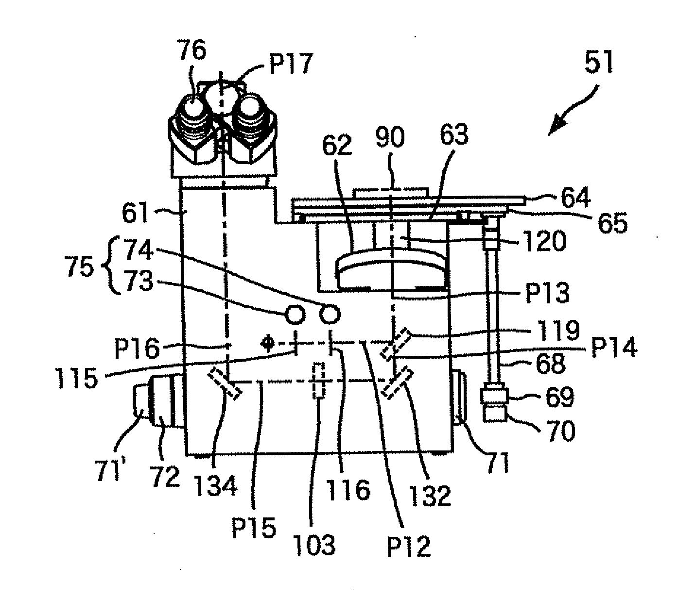
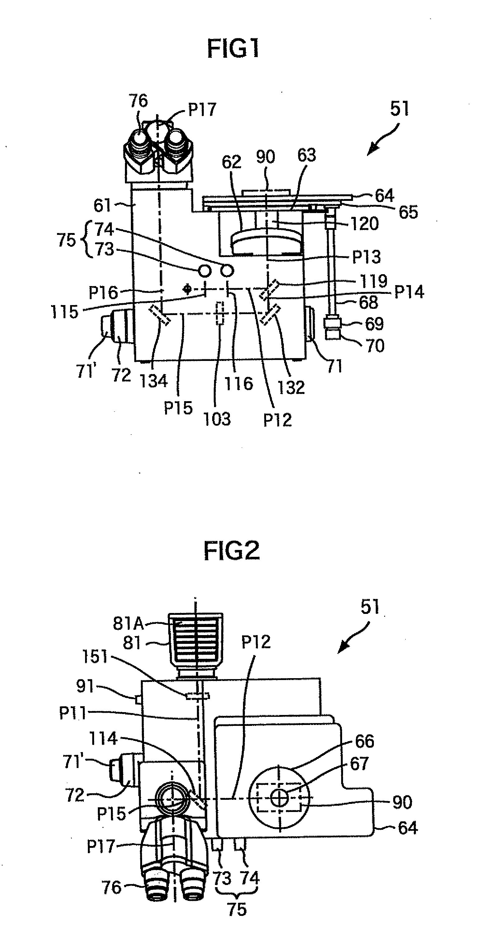
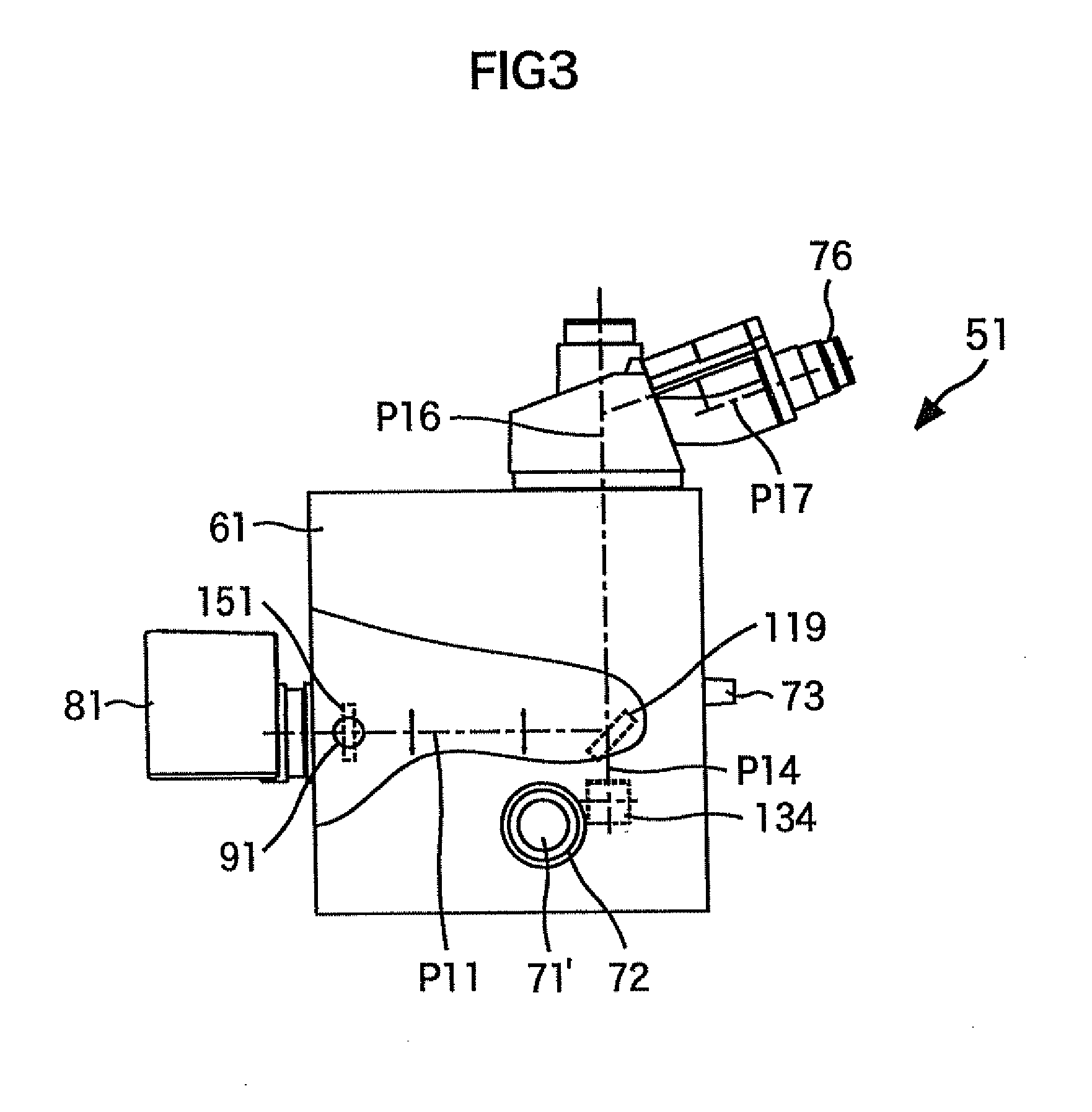
[0049]FIG. 1 to FIG. 3 show a configuration of an embodiment of a microscope to which the present invention is applied. A revolver 62 is rotatably disposed at the upper right of the main body 61 of the microscope 51. Some objective lenses can be removably attached to this revolver 62, and the user can select an objective lens to be used by rotating the revolver 62 when necessary, and positioning a desired objective lens, out of the attached objective lenses, at a predetermined position. FIG. 1 shows a state where only one objective lens 120 is attached.

[0050]A stationary plate 63 is horizontally disposed on the main body 61 above the revolver 62. Stages 64 and 65 are disposed along the X axis (horizontal direction in FIG. 2) and the Y axis (vertical direction in FIG. 2) respectively, with respect to the stationary plate 63, so as to be freely moved. At the bottom of an adjustment axis 68 ...


PUM


Abstract

The present invention relates to a microscope of which visibility, controllability and operability can be improved.In the microscope, an optical path and optical path of an image forming system are set so as to be perpendicular to each other when viewed from the top. In other words, in this microscope, there exists an ocular optical system that guides light, which propagates the optical path to optical path of the image forming system, to a user. The optical path is formed in a direction perpendicular to a direction of the light from a sample emitted from the ocular optical system to the user. The present invention can be applied to an inverted microscope.

Description

[0001]This is a Continuation of application Ser. No. 12 / 671,624 filed Feb. 1, 2012, which in turn is a National Stage of Application No. PCT / JP2008-064143, filed Aug. 6, 2008. The disclosure of the prior application is hereby incorporated by reference herein in its entirety.TECHNICAL FIELD[0002]The present invention relates to a microscope, and more particularly to a microscope of which visibility, controllability and operability are improved.BACKGROUND ART[0003]Conventionally in an image forming optical system of an inverted microscope, there are an optical axis of an objective lens (hereafter referred to as an “objective optical axis”), and an optical axis constituting a part of an image forming optical path at a lens barrel side (hereafter referred to as a “lens barrel optical axis”). These objective optical axis and lens barrel optical axis are positioned at the center of the microscope unit (hereafter referred to as the “main body portion”), and are often disposed in parallel a...

Claims


Application Information

Patent Timeline
Patent Type & Authority Applications(United States)
IPC IPC(8): G02B21/08G02B21/06
CPCG02B21/0088G02B21/361G02B21/24
Inventor MURAYAMA, TORUTAKEUCHI, ATSUSHIOUCHI, YUMIKOYOSHIDA, YUKI
Owner NIKON CORP
Learn More