Insert, plastic part assembly utilizing same and die-casting mold for making the insert

a technology of inserts and plastic parts, applied in the direction of electric/fluid circuits, propulsion parts, vehicle components, etc., can solve the problems of screw loosening, plastic materials under, deformation or narrowing, etc., and achieve the effect of cheap and simple die-casting process

Active Publication Date: 2013-10-22
LEAR CORP
View PDF18 Cites 3 Cited by
  • Summary
  • Abstract
  • Description
  • Claims
  • Application Information

AI Technical Summary

Benefits of technology

[0013]An object of the present invention is to provide a molded metal insert, a plastic part assembly utilizing the insert, and a die-casting mold for making such an insert, wherein the insert includes anti-rotation metal “teeth” which are molded in a cheap and simple die-cast process and mold. The “teeth” sides are oriented or shaped in a way that the inserts can be molded in a single die-cast, two-part mold.
[0016]The teeth may not radially extend beyond the outer diameter so that the upper and lower end portions protect the teeth.
[0023]The teeth may not radially extend beyond the outer diameter so that the upper and lower end portions protect the teeth.

Problems solved by technology

Nevertheless, although a “well designed” plastic “ear” is enough to ensure robustness for such attachment, all plastic materials under pressure, (here from the attachment screw), suffer some deformation or “narrowing” with aging.
This “narrowing” causes the screw to become loose or, what, in turn, causes the box to become loose.
However, a round metal ring molded with its plastic part may “rotate” when the screw is screwed into the vehicle's frame.
This often produces undesired scratches in the plastic, or the metal ring can come loose if the part is disassembled.
Then there is no better solution than a bigger round hole.
However, present day requirements from customers require high screwing forces, and that the metal piece or ring not rotate in the plastic hole of the box.
However, this is a quite expensive solution.

Method used


Image

  • Insert, plastic part assembly utilizing same and die-casting mold for making the insert
  • Insert, plastic part assembly utilizing same and die-casting mold for making the insert
  • Insert, plastic part assembly utilizing same and die-casting mold for making the insert

Examples


Embodiment Construction

)

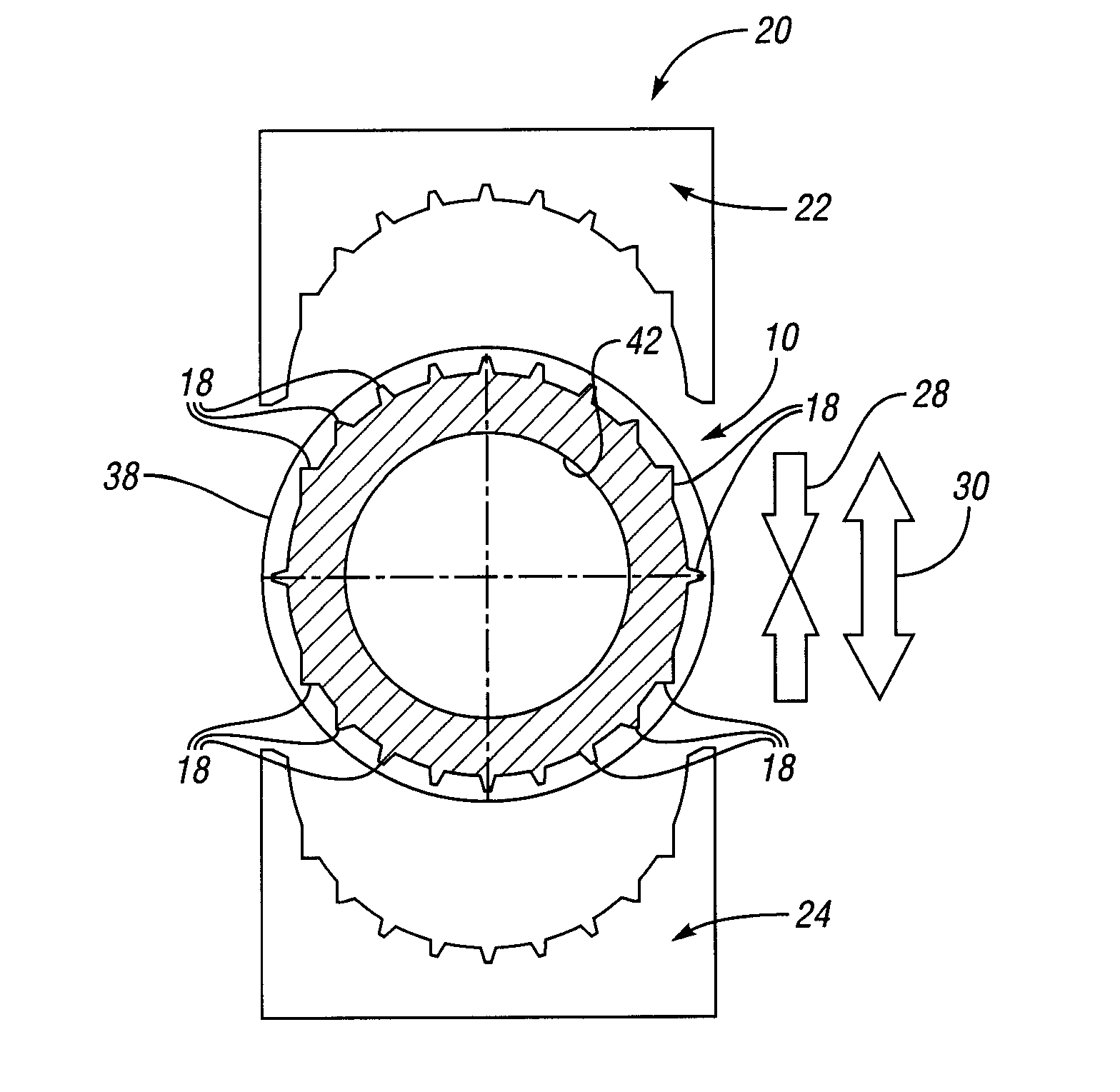
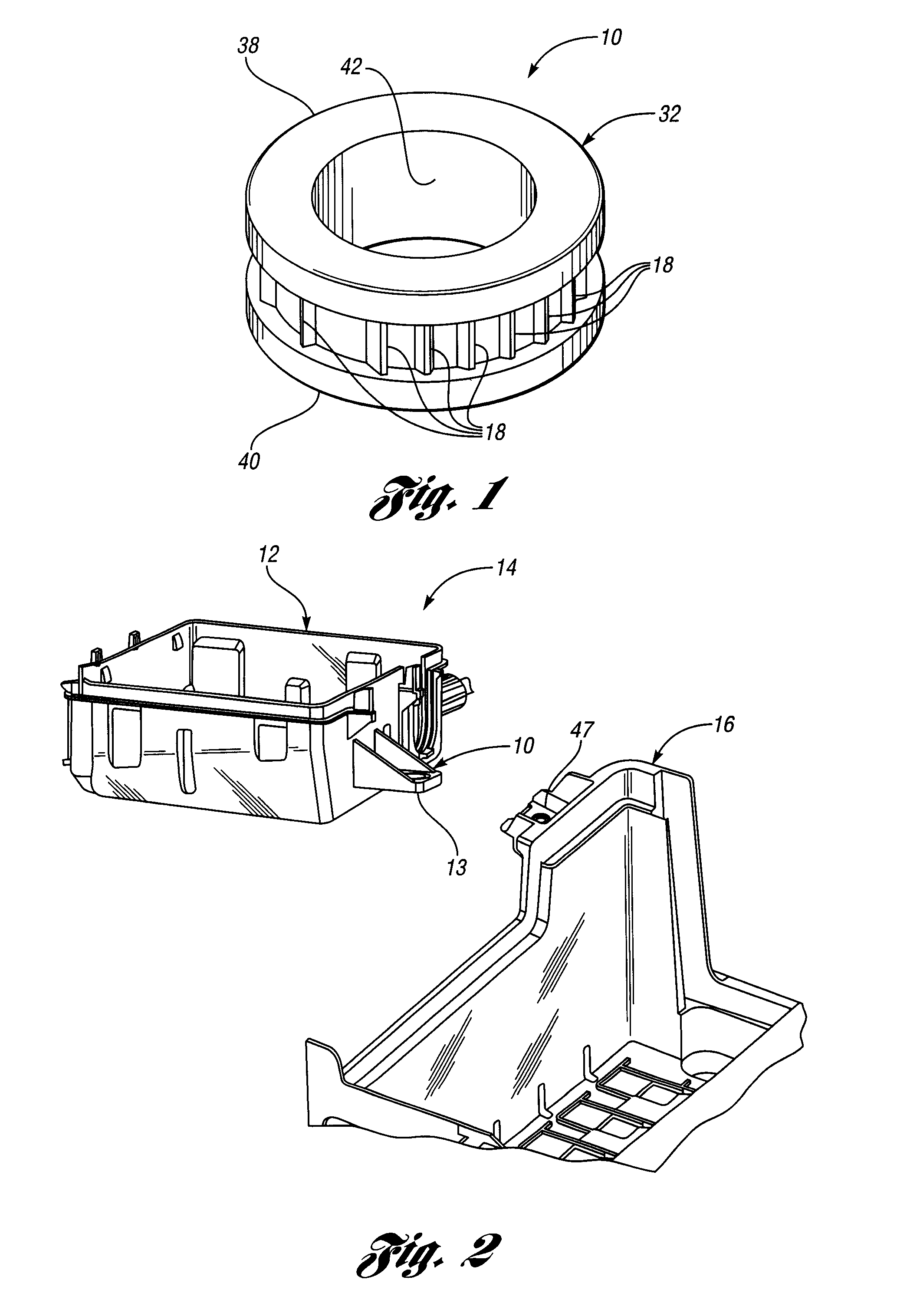
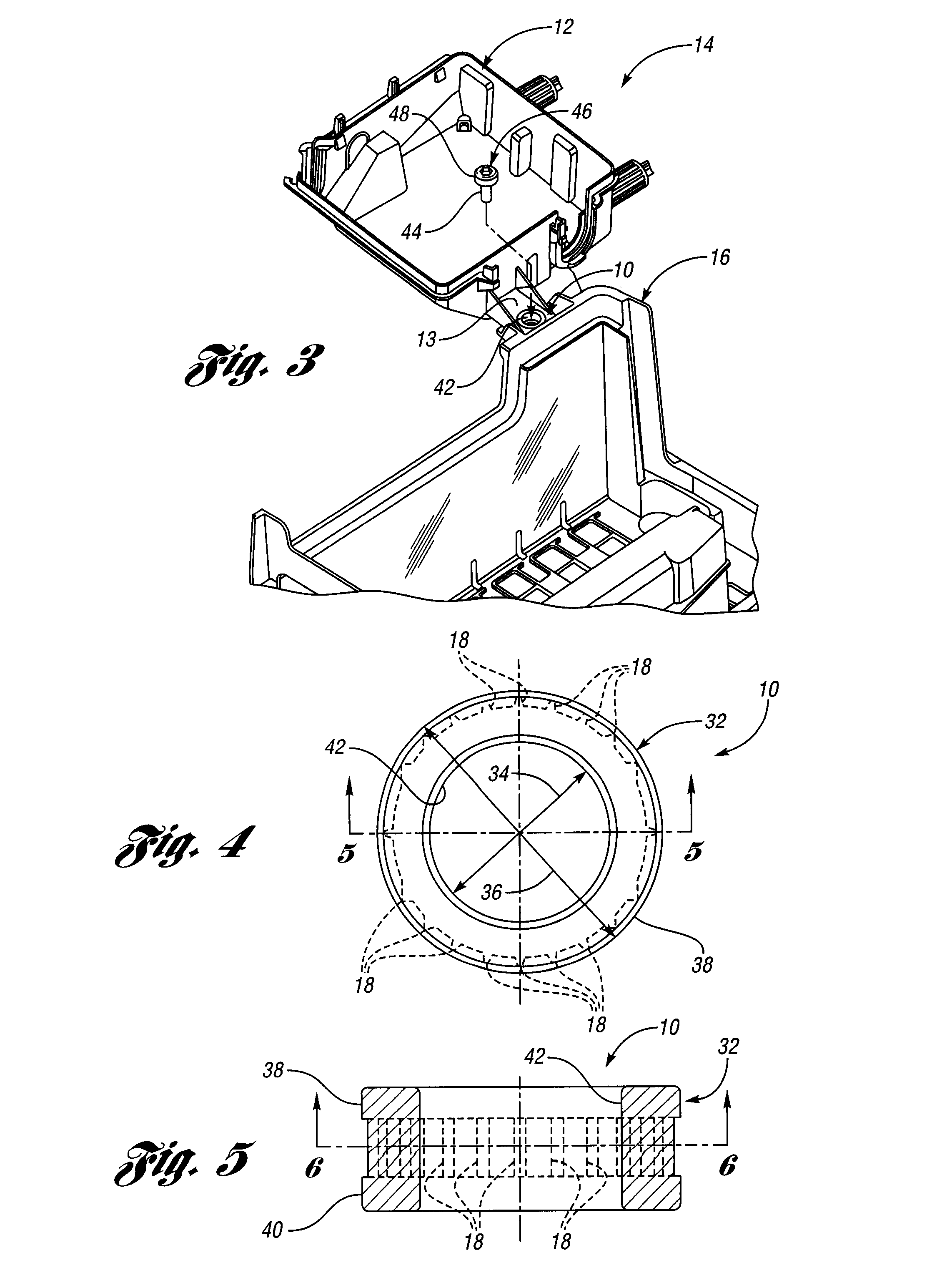
[0038]In general, one embodiment of the present invention provides a molded metal insert, generally indicated at 10 in FIG. 1, and a plastic part, such as a plastic housing generally indicated at 12, of an electric box, integrally formed with the insert 10 to form an assembly, generally indicated at 14, which, in turn, is attached and fixed to a vehicle structure such as a battery support, generally indicated at 16. The insert or grommet 10 includes teeth 18 to prevent rotation of the insert 10 relative to the plastic part 12. The teeth 18 are sized and shaped in a way that simple die-casting of the insert 10 is possible. A die-casting die or mold constructed in accordance with one embodiment of the invention is generally indicated at 20 in FIG. 6, and has only two parts 22 and 24 which define an article-defining cavity for forming the insert 10. Movement of the parts or mold halves 22 and 24 is indicated by the vertical lines 26 and arrows 28 and 30 in FIG. 6. The teeth 18 are sha...


PUM


Abstract

A molded metal insert and plastic part integrally formed therewith form an assembly wherein the insert is provided with anti-rotation, die-cast teeth. The insert is adapted to attach and fix the plastic part to a vehicle structure in combination with a threaded fastener. The insert includes a cylindrical metal body having inner and outer diameters and upper and lower end portions. The inner diameter defines a passageway sized to allow an externally threaded portion of the fastener to extend through the passage and below the lower end portion for threaded attachment to the vehicle structure. The upper end portion provides a seat for a head of the fastener. The anti-rotation metal teeth are integrally molded with and extend radially outwardly from the cylindrical metal body between the inner and outer diameters and between the upper and lower end portions wherein the upper and lower end portions protect the teeth. A die-casting mold for forming the insert is also provided.

Description

CROSS-REFERENCE TO RELATED APPLICATIONS[0001]This application is related to U.S. patent application entitled “Junction Box Assembly” filed on the same day as this application and having U.S. Ser. No. 11 / 538,929, which issued as U.S. 7,459,630.BACKGROUND OF THE INVENTION[0002]1. Field of the Invention[0003]This invention is related to a molded metal inserts, plastic part assemblies utilizing such inserts and die-casting molds for making same inserts. The present invention may be applied to a plastic electrical box (i.e., junction box, electronic box) or plastic housing that requires a robust attachment to a vehicle structure.[0004]2. Background Art[0005]Electric boxes utilized in automotive vehicles, such as junction electronic boxes which have a plastic housing, need to be fixed to such vehicles, normally with screws. For this reason, the boxes must have some external elements like “ears” or flanges, that is, flat parts with a hole in them, so that a screw is inserted through them a...

Claims


Application Information

Patent Timeline
Patent Type & Authority Patents(United States)
IPC IPC(8): B60R16/04
CPCB60R16/04
Inventor PEDRET, MONTSERRAT PINOLCACERES, RAMON AGUILA
Owner LEAR CORP
Why Eureka
Try Eureka