Vehicle handle apparatus

a technology for handling devices and vehicles, applied in mechanical devices, locking applications, fastening means, etc., can solve problems such as poor appearance, and achieve the effect of not deteriorating an appearan

Active Publication Date: 2013-10-22
ALPHA
View PDF2 Cites 9 Cited by
  • Summary
  • Abstract
  • Description
  • Claims
  • Application Information

AI Technical Summary

Benefits of technology

[0008]One or more embodiments of the invention provides a door handle apparatus for a vehicle which can prevent a shake of an operating handle in a pull-out position without deteriorating an appearance.
[0012]By further extending the operating leg 5 from the stopper protrusion 4 in a direction of a free end to form the shake preventing protrusion 6 on the free end, it is possible to set the interval between the first and second guide portions 7 and 8 to be larger. Therefore, it is possible to decrease a shaking angle of the operating handle 2. Thus, it is possible to decrease an amount of the shake.
[0016]In the embodiments of the invention, the stopper protrusion 4 extends to the back side to form the shake preventing protrusion 6 on the free end. Furthermore, in the handle base 1, there is provided the second guide portion 8 for regulating a movement in a shaking direction of the shake preventing protrusion 6 when the operating handle 2 rotates and is operated up to the pull-out position. Thus, the shake preventing protrusion 6 is considered to reliably function. As a result, it is possible to reliably ensure the interval between the first and second guide portions 7 and 8. Consequently, it is possible to effectively prevent the shake.
[0017]In the case in which a cover piece 9 for forming the second guide portion 8 is extended in a direction of the back face and is thus caused to correspond to a rear edge of the operating leg 5 when the operating handle 2 is placed in the initial position, it is desirable to ensure a sufficient water flowing gap 10 between an internal wall surface of the cover piece 9 and the shake preventing protrusion 6. The water flowing gap 10 is disposed for preventing an operation of the operating handle 2 from being carried out with difficulty due to freezing of waterdrops entering a part between the cover piece 9 and the shake preventing protrusion 6, and can be formed by providing a sufficient interval for non-adhesion of the waterdrops to both of wall surfaces through a surface tension or an elimination of the adhesion state in a comparatively early stage by dropping or flow if any between the internal wall surface of the cover piece 9 and a sidewall surface of the shake preventing protrusion 6.
[0018]Although the water flowing gap 10 can also be formed stepwise, if the water flowing gap 10 is formed by a continuous inclined surface, it is possible to reliably prevent catching in an operation. In this case, it is possible to easily form the water flowing gap 10 by setting an internal wall surface reaching the free end of the cover piece 9 from a termination on the free end side of the second guide portion 8 in the cover piece 9 to be a surface having a large gradient.
[0019]According to the structure of the embodiments of the invention, it is possible to regulate a shake of an operating handle in a pull-out position without deteriorating an appearance in a pull-out operation of the operating handle in order to prevent the shake by utilizing an internal space of a door.

Problems solved by technology

Therefore, there is a problem in that the guide wall portion protruding from the handle base is exposed to an outside in the pull-out of the operating handle, which causes a poor appearance.

Method used


Image

  • Vehicle handle apparatus
  • Vehicle handle apparatus
  • Vehicle handle apparatus

Examples


Embodiment Construction

[0034]An exemplary embodiment of the invention is described with reference to drawings.

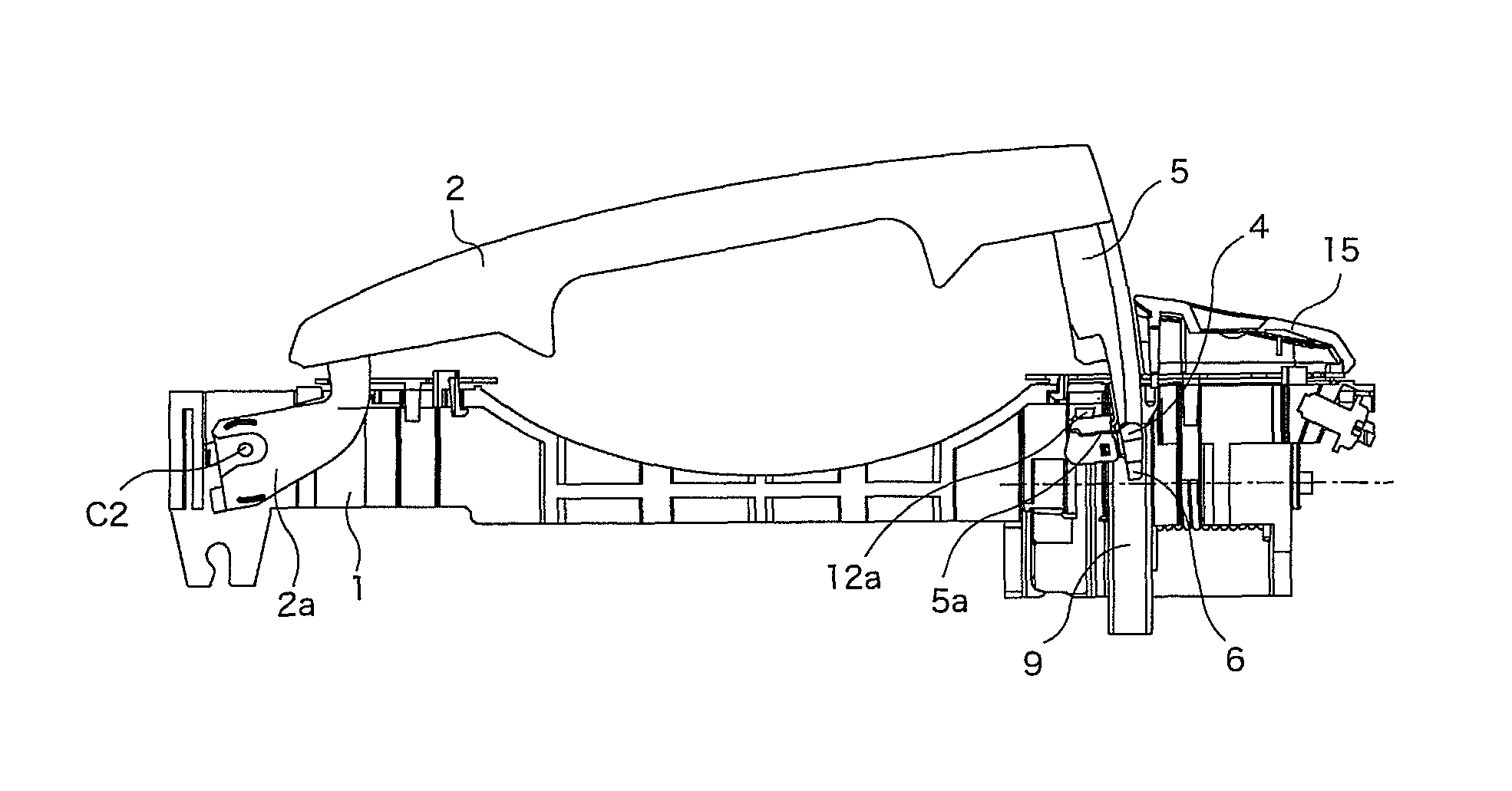
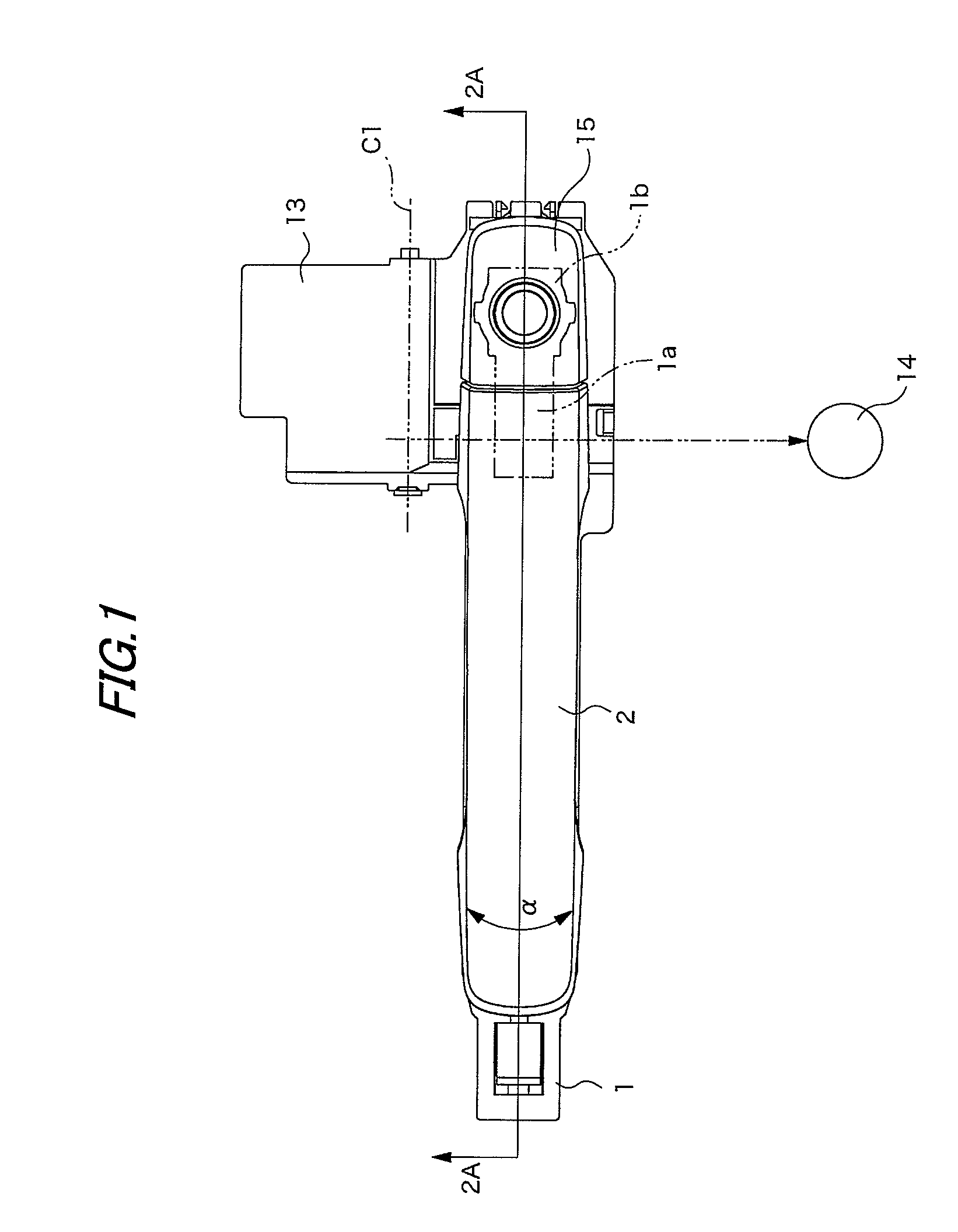
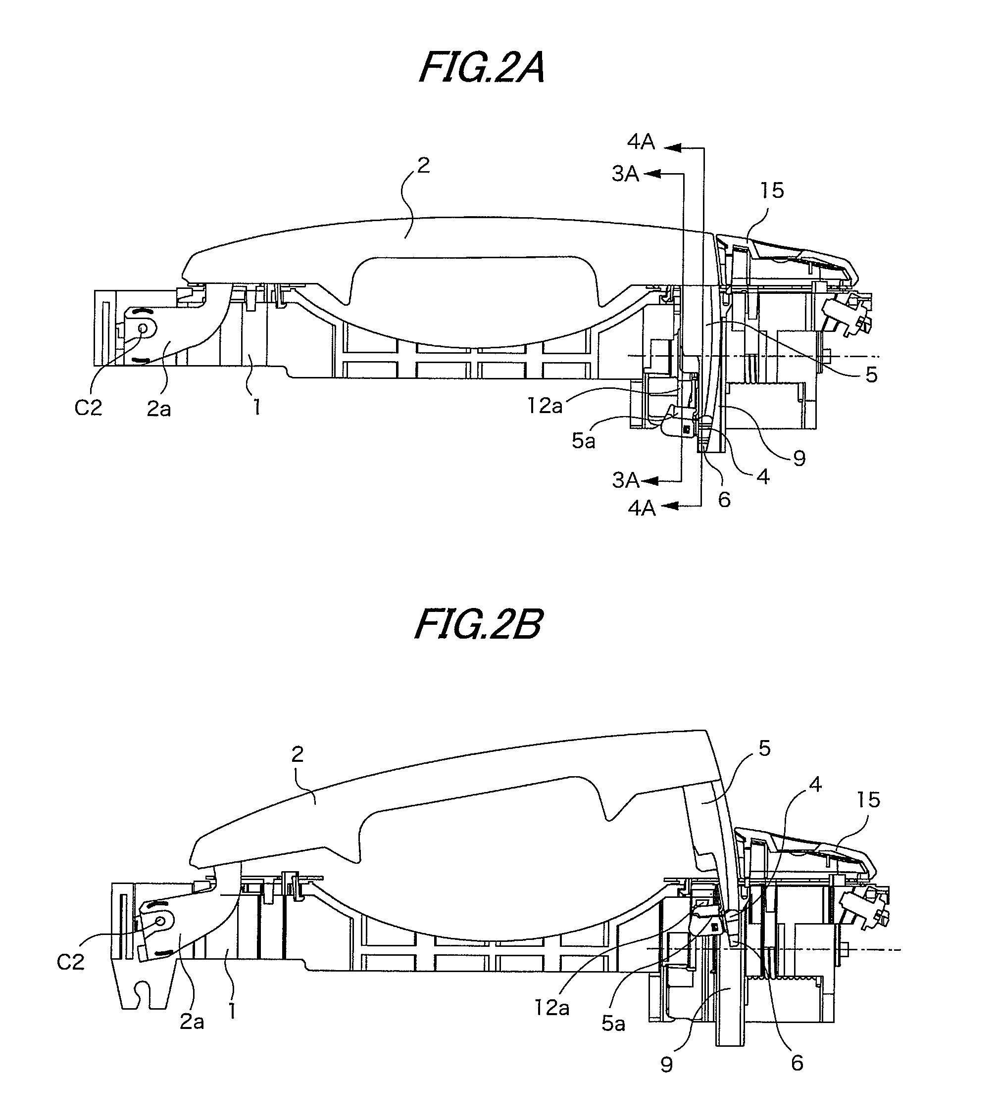
[0035]As shown in FIG. 1 and subsequent drawings, a handle apparatus includes a handle base 1 and an operating handle 2 having one end which is pivotally coupled to the handle base 1. The handle apparatus is attached to a door in such a posture that a left side in FIG. 1 directs to a front side of a vehicle.

[0036]The operating handle 2 includes a hinge protrusion 2a on a front end (the direction of the front side of the vehicle will be hereinafter referred to as “front” based on an attaching posture to the vehicle) and an operating leg 5 on a rear end. Thus, the operating handle 2 is constituted as an operating handle of a so-called gripping type in which a central part is grasped to carry out an operation. The operating handle 2 is pivotally coupled to the handle base 1 at the hinge protrusion 2a. The operating leg 5 is inserted and attached into an inner part of a door. The operating leg 5 is mo...


PUM


Abstract

A door handle apparatus for a vehicle is provided with a handle base to be fixed to a door of the vehicle and an operating handle. One end of the operating handle is pivotally coupled to the handle base. On the other end of the operating handle, an operating leg protrudes. The operating leg portion includes a stopper protrusion for butting with a part of the handle base to define a termination of a rotating stroke of the operating handle is provided. The operating leg portion further includes a shake preventing protrusion on a free end side of the stopper protrusion.

Description

BACKGROUND OF THE INVENTION[0001]1. Field of the Invention[0002]The present invention relates to a handle apparatus for a vehicle.[0003]2. Background Art[0004]JP-A-2008-013962 discloses a handle apparatus of a so-called gripping type in which a gripping portion formed in an intermediate part of an operating handle is held to open / close a door. In the handle apparatus, a guide arm portion (an operating leg) protrudes from a rotating end of the operating handle having the other end which is pivotally coupled to a base member (a handle base). The guide arm is inserted into a rotation guiding portion of the handle base.[0005]A free end of the operating leg is provided with a slip preventing portion, and a stroke termination on a pull-out side of the operating handle is defined by an abutment of the slip preventing portion with a stopper portion formed in the rotation guiding portion.[0006]Moreover, a guide wall portion protrudes from the handle base. In the case in which the operating h...

Claims


Application Information

Patent Timeline
Patent Type & Authority Patents(United States)
IPC IPC(8): E05B63/20
CPCE05B85/16E05B15/1635Y10T292/0908Y10T292/57
Inventor ICHIKAWA, SHINJIMINEMURA, RYUJI
Owner ALPHA
Why Eureka
Try Eureka