Clamping arrangement and ejector and conical ring for the same

a technology of ejector ring and conical ring, which is applied in the direction of couplings, rod connections, manufacturing tools, etc., can solve the problems of limiting the number of clamping screws, inability of such clamping arrangements to transmit sufficiently high torque, and weakening the mechanical load capacity of the conical ring, so as to allow the periphery to adap

Active Publication Date: 2013-10-22
BIKON TECH GMBH
View PDF26 Cites 6 Cited by
  • Summary
  • Abstract
  • Description
  • Claims
  • Application Information

AI Technical Summary

Benefits of technology

[0013]Accordingly, a clamping arrangement according to claim 1 is provided, in which several through bore-holes for clamping screws have an ejector thread for screwing in ejector screws. Thus the already provided through bore-holes for clamping screws are according to the invention also used for ejector screws. Additional ejector screw threaded bores are no longer necessary. The number of clamping screws usable for bracing the clamping arrangement therefore remains unchanged. Moreover, no additional bores between the bores for the clamping screws are necessary, so that the conical ring is not weakened. According to the invention, it is thus possible to use the largest possible number of clamping screws to increase the maximum transferable torque, where the clamping arrangement is not weakened by additional bores, and disassembly can be done in a simple way.
[0016]The mutually applied surfaces of the inner conical ring and of the inner component arrangement can be in the shape of a circular cylinder or of a cone. The same applies for the mutually applied surfaces of the outer conical ring and of the outer component arrangement. As a result, an optimal adaptation to the geometry of the outer and / or inner component arrangement is possible.
[0018]The bores are here advantageously distributed equally along the periphery. This has the result of a homogeneous stress distribution. It is advantageous here for each second, third or fourth bore to have an ejector thread for the leadthrough of a clamping screw, so that the ejector screws are also distributed equally, and the ejector surfaces arranged in between are not overloaded.
[0020]It is advantageous to provide tool bores in the ejector ring for the leadthrough of a screw tool through an ejector surface. As a result, clamping screws can be loosened further or screwed in again without again having to take off the ejector ring. The result is a simple way to adjust the clamping screws during the ejection.
[0022]The ejector ring as well as the conical rings can be closed or interrupted along their periphery by a slit. The slit allows adaptability of the periphery during clamping.
[0023]The ejector ring can be subdivided along its periphery into at least two sections. As a result, it is lighter and can also be used when the circumstances of the construction make it difficult or impossible to slip a closed ring on a shaft.

Problems solved by technology

However, this solution is associated with the disadvantage that the threaded ejector bores limit the number of clamping screws that can be used in the peripheral direction.
This leads, particularly in the case of small diameters, to the inability of such clamping arrangements to be able to transmit sufficiently high torques.
However, this solution weakens the mechanical load capacity of the conical ring, because the webs between the clamping screw bores and the threaded ejector bores become very small.

Method used


Image

  • Clamping arrangement and ejector and conical ring for the same
  • Clamping arrangement and ejector and conical ring for the same
  • Clamping arrangement and ejector and conical ring for the same

Examples


Embodiment Construction

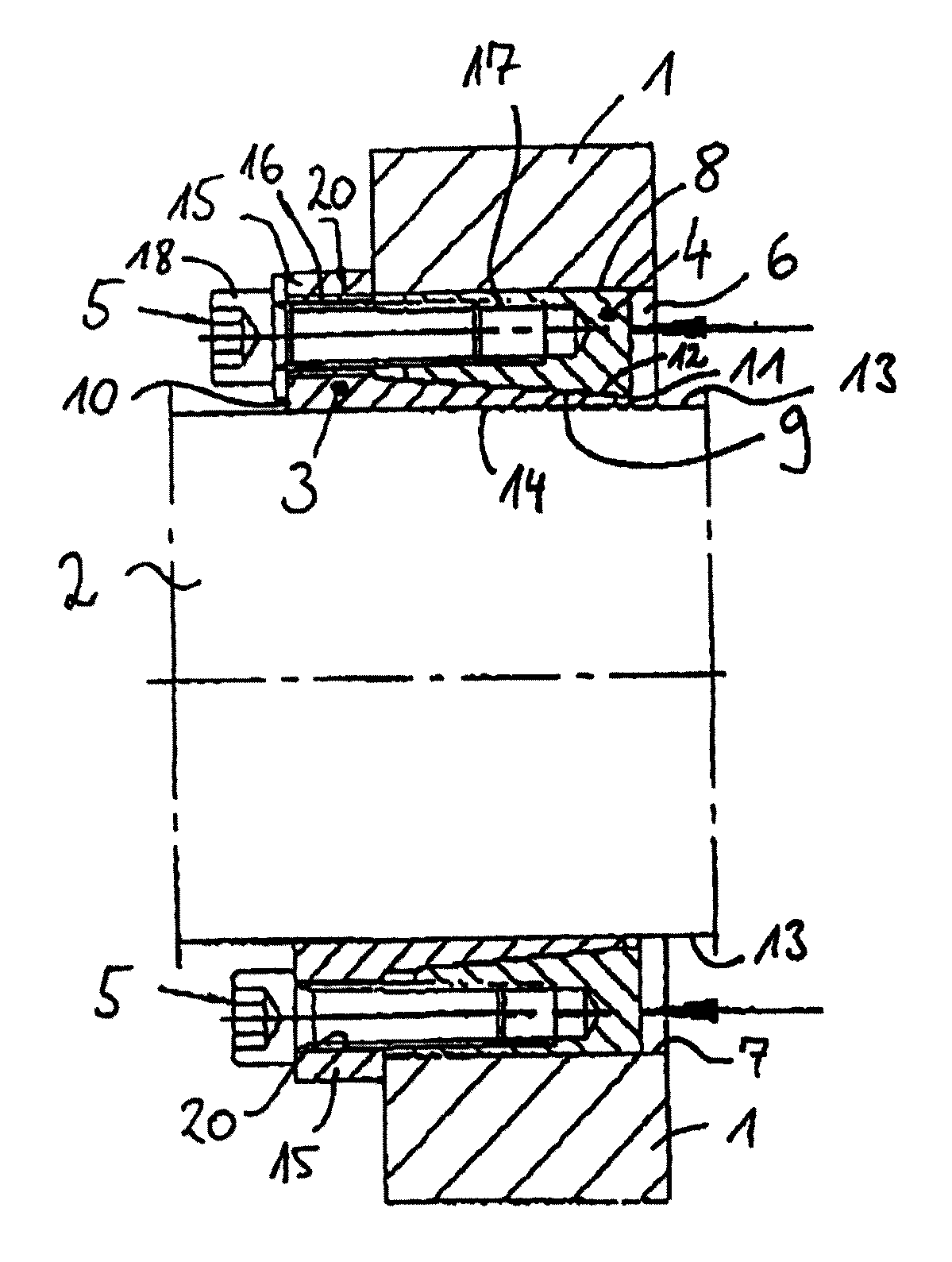
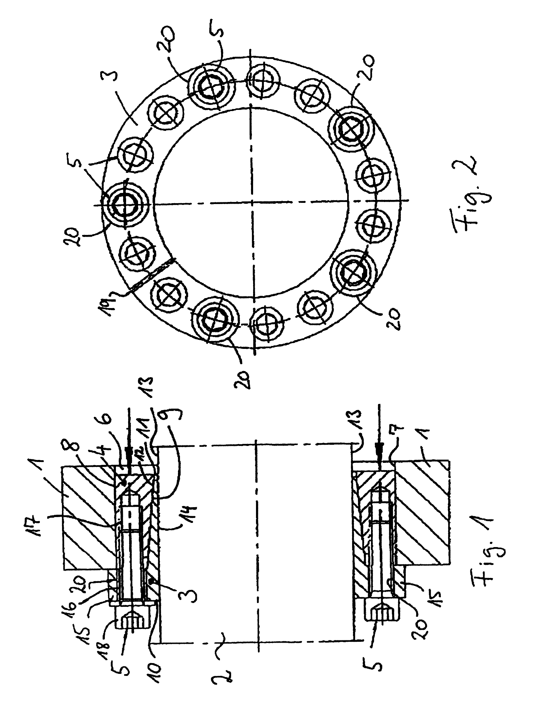
[0037]Referring now to the drawings wherein the showings are for the purpose of illustrating preferred and alternative embodiments of the invention only and not for the purpose of limiting same, FIGS. 1 and 2 shows a clamping arrangement to obtain a force-fit connection between a hub 1 and a shaft 2. More particularly, shown are an inner and an outer conical ring 3, 4 a that are braced by means of clamping screws 5 against one another, and against the hub 1 and the shaft 2.

[0038]For this purpose, the hub 1 has a recess 6, into which the shaft 2 with attached conical rings 3, 4 is inserted. The recess 6 forms a cylindrical surface 7 that faces the shaft 2, and is designed here advantageously in the shape of a circular cylinder. The cylindrical surface 7 can also be designed to be conical, or in another advantageous way.

[0039]A peripheral surface 8, here also circular cylindrical, of the outer conical ring 4 comes in contact with the cylindrical surface 7. A conical peripheral surface...


PUM


Abstract

A clamping arrangement for the force-fit connection of an outer component to an inner component including an inner conical ring and an outer conical ring wherein one of the rings has leadthrough bores clamping screws and the other ring has threaded bores for the clamping screws to brace the rings against one another via the conical peripheral surfaces, and against the inner and outer component arrangement. At least one leadthrough bore having an ejector thread for an ejector screw and the diameter of the ejector thread being greater than the diameter of the clamping screw. The arrangement including an ejector ring with an ejector bore for the leadthrough of the ejector screw which can be screwed into the ejector thread and an ejector surface for engaging a clamping screw head that is incompletely screwed into the corresponding threaded bore for the transmission of an ejector force onto the clamping screw.

Description

[0001]This application claims priority to and the benefit of the filing date of International Application No. PCT / EP2008 / 006358, filed Aug. 1, 2008, which application claims priority to and the benefit of the filing date of German Application No. 20 2007 010 709.9, filed Aug. 1, 2007, both of which are hereby incorporated by reference into the specification of this application.FIELD OF THE INVENTION[0002]The invention relates to a clamping arrangement and an ejector ring and a conical ring for the same and, more particularly, to a clamping arrangement for the force-fit connection of an outer component arrangement to an inner component arrangement; and components therefor.BACKGROUND OF THE INVENTION[0003]Such detachable clamping arrangements are used for the force-fit connection of two components, particularly a shaft and a hub. For this purpose, they are positioned between the shaft and the hub, and then clamped. They allow the transmission of high torques and, as the case may be, a...

Claims


Application Information

Patent Timeline
Patent Type & Authority Patents(United States)
IPC IPC(8): F16B2/00
CPCF16D1/094F16D2001/0945Y10T403/1641Y10T403/7056Y10T403/635Y10T403/7069
Inventor DIZDAREVIC, ZLATKO
Owner BIKON TECH GMBH
Why Eureka
Try Eureka