Shot-blasting machine for surface treatment of products

a technology of surface treatment and product, which is applied in the direction of blast generating device, abrasive machine appurtenance, blast generating device, etc., can solve the problems of small-rewarding and at times tiring work operations, the size of articulated robots is considerably larger, and the cost of repetitive work is irrelevant, etc., to achieve the effect of limited siz

Active Publication Date: 2013-10-22
C M SURFACE TREATMENT
View PDF10 Cites 2 Cited by
  • Summary
  • Abstract
  • Description
  • Claims
  • Application Information

AI Technical Summary

Benefits of technology

[0016]The main aim of the present invention is to provide a shot-blasting machine for surface treatment of products, which machine treats a large number of products in a practical, simple and functional way, without any need for substantial use of personnel and which, at the same time, is of an especially limited size.
[0017]A further object of the present invention is to operate with very contained installation, management and maintenance costs.
[0018]A further object of the present invention is to provide a shot-blasting machine for surface treatment of products which enables the above-mentioned drawbacks in the prior art to be obviated, with a simple and rational solution which is also simple and effective to use.

Problems solved by technology

This manual activity, however, has various drawbacks, such as e.g. the need to have available the actual member of personnel, leading to a relevant cost for what are after all repetitive, little-rewarding and at times tiring work operations.
This product loading and unloading system is also not without drawbacks.
One drawback is that articulated robots have considerably space-consuming dimensions and in order to operate they require a certain amount of working space in the vicinity thereof.
This drawback is particularly noted in those plants in which a large number of products have to be moved rapidly, and in which for this aim fork-lift trucks or other lifting devices are used, which require large maneuvering spaces and wide avenues to move in.
Another noteworthy point is that plants equipped with articulated robots are subject to particularly high installation, control / management and maintenance costs, which have a negative influence on the final cost of the treated products.
It is also stressed that the need to combine two separate machines, i.e. a shot-blaster and an articulated robot, leads to the inconvenient need to connect and interface the operation of one machine with that of the other, and this operation is not always rapid and immediate to set up.

Method used


Image

  • Shot-blasting machine for surface treatment of products
  • Shot-blasting machine for surface treatment of products
  • Shot-blasting machine for surface treatment of products

Examples


Embodiment Construction

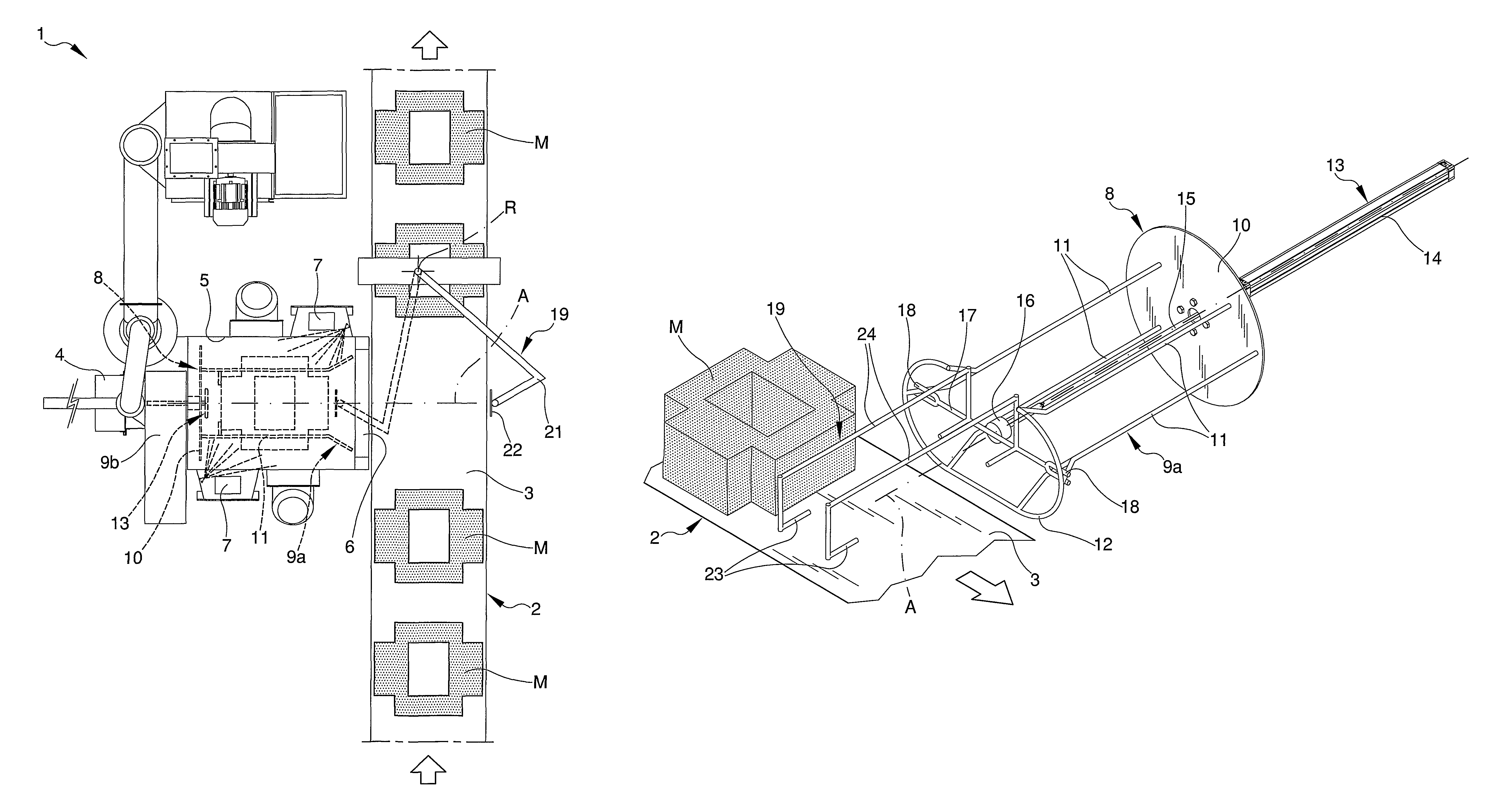
[0028]With special reference to the figures of the drawings, 1 denotes in its entirety a shot-blasting machine for surface treatment of products.

[0029]The machine 1 is destined to be associated to an advancement line 2 of products M to be treated, e.g. a conveyor belt or a roller plane.

[0030]The advancement line 2 defines in practice a substantially horizontal plane 3 for moving the products M.

[0031]In more detail, the machine 1 comprises a base frame 4 which supports a containing chamber 5 for containing the products M which is arranged by a side of the advancement line 2.

[0032]An access opening 6 is afforded on a wall of the chamber 5 which wall faces the advancement line 2 of the products M, through which opening 6 the products M can both enter and exit the chamber 5.

[0033]The access opening 6 is arranged substantially at the same height from the ground as the plane 3, such that at least a portion of the advancement line 2 is arranged in front of the access opening 6.

[0034]A seri...


PUM


Abstract

The shot-blasting machine for surface treatment of products comprises a base frame, a containing chamber for containing at least a product to be treated associated to the base frame and provided with at least an access opening, one or more projecting organs associated internally of the chamber for projecting a flow of shot-blasting particles onto the product, and automated unloading means associated to the base frame which cause the product to exit from the chamber through the access opening.

Description

CROSS REFERENCE TO RELATED APPLICATIONS[0001]This application is the National Stage of PCT / IB2008 / 001879 filed on Jul. 18, 2008, which claims priority under 35 U.S.C. §119 of Italian Application No. MO2007A000249 filed on Jul. 27, 2007.TECHNICAL FIELD[0002]The invention relates to a shot-blasting machine for surface treatment of products.PRIOR ART[0003]As is known, shot-blasting machines, using a compressed-air propelling system, or a system based on centrifugal force, project particles against a surface of one or more products, generating a surface treatment which can be cleaning, roughening, deburring and / or hardening (shot-peening).[0004]The particles which are projected against the products are usually generically known as “grit”, and consist in an abrasive mixture of sand, pumice, glass, steel shots and / or other materials of various granulometry according to the type of finishing required.[0005]The fields of use of the machines are very varied indeed, according to the type of t...

Claims


Application Information

Patent Timeline
Patent Type & Authority Patents(United States)
IPC IPC(8): B24C3/08
CPCB24C3/083B24C3/085B24C3/26
Inventor GIOVANARDI, PAOLA
Owner C M SURFACE TREATMENT
Why Eureka
Try Eureka