
Personal escape device and methods for using same

a technology of personal escape device and escape device, which is applied in the direction of safety belt, hoisting equipment, sport apparatus, etc., can solve the problems of increasing violent crime rampages, terrorism, and the risk of life of firefighters and police, and avoiding the use of a large number of peopl

Active Publication Date: 2013-10-29
STONES THROW
View PDF33 Cites 30 Cited by
  • Summary
  • Abstract
  • Description
  • Claims
  • Application Information

AI Technical Summary

Benefits of technology

Enables safe, controlled descent for individuals of varying ages and abilities by maintaining reliability and functionality over time, accommodating different weights and abilities, and providing a compact storage solution with integrated safety features.

Problems solved by technology

Hundreds of firefighters and police risk their life every day by entering burning buildings to save trapped civilians.
Additionally, terrorism, hostage situations, and violent crime rampages worldwide are increasing, often leaving people trapped high above the streets, waiting for rescue.
For many fire victims, exit routes are too slow or inaccessible due to extremely hot flames and smoke.
For overweight or physically impaired individuals, stairs are not an option.
Too frequently victims are trapped and forced to wait for rescue.
Such devices have a relatively short life, depending on the nature of the fluid, and risk failure due to low or insufficient fluid levels.
However, wear on the rope caused by the friction of the manual braking system makes such a system dependent upon the abilities of the user, thus are less reliable for members of the population who do not have the capacity to exert sufficient force to slow the descent.
Yet other prior art devices include a complexity of mechanics to make them unwieldy and inherently less reliable.
Not only are such complex mechanisms expensive to manufacture, the multiple parts makes them inherently unreliable.
Similarly, prior art devices that include spring mechanisms, such as that found in U.S. Pat. No. 3,760,910, include an element that may not store over time, may break under certain heavier weights, or may not extend sufficiently under certain lighter weights.

Method used


Image

  • Personal escape device and methods for using same
  • Personal escape device and methods for using same
  • Personal escape device and methods for using same

Examples


Embodiment Construction

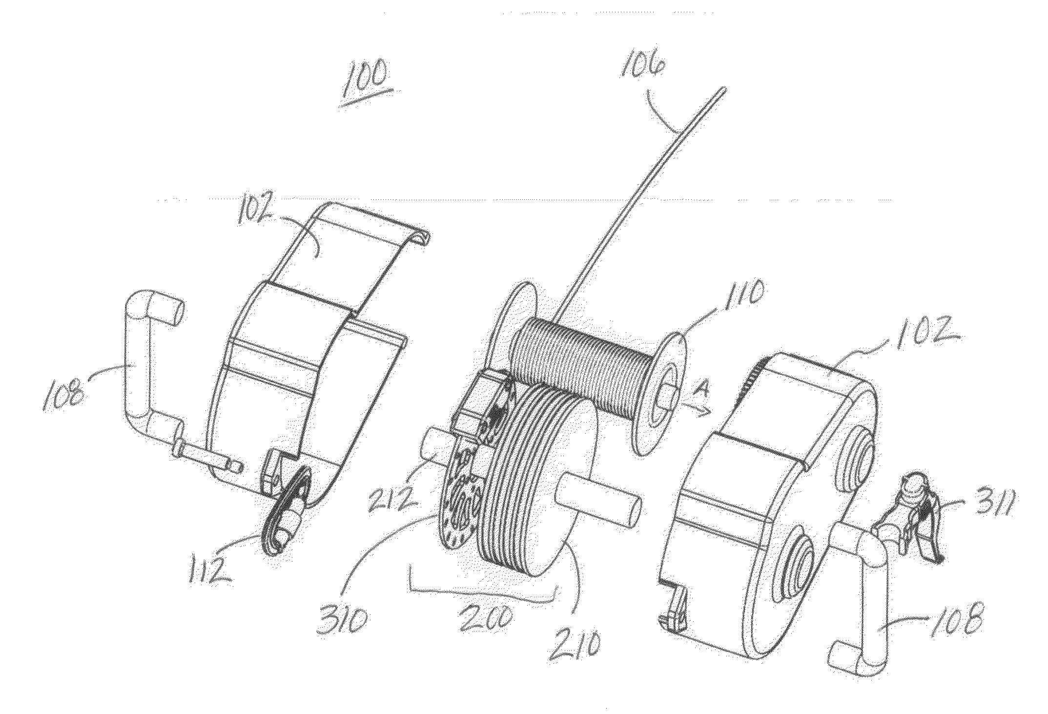
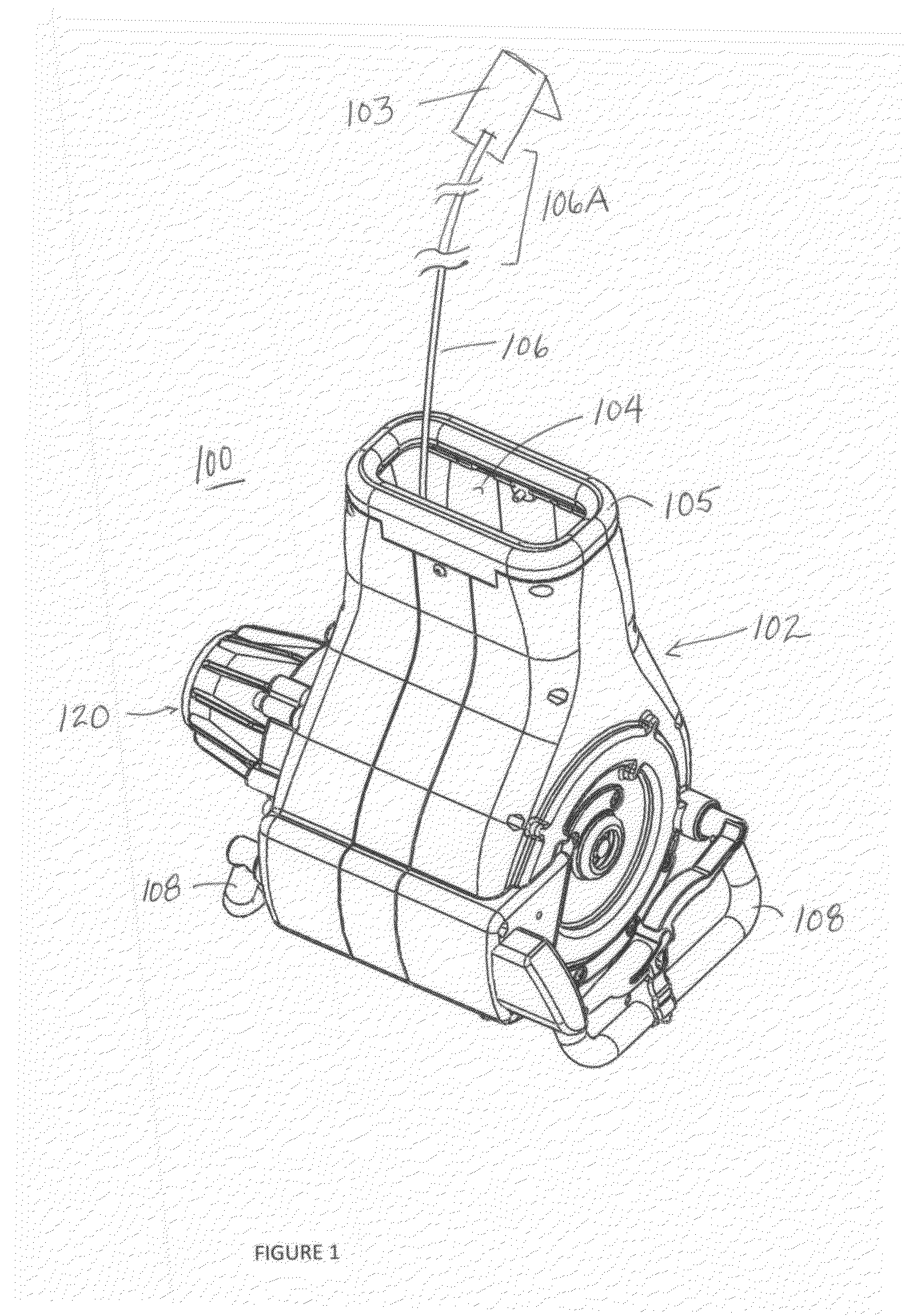
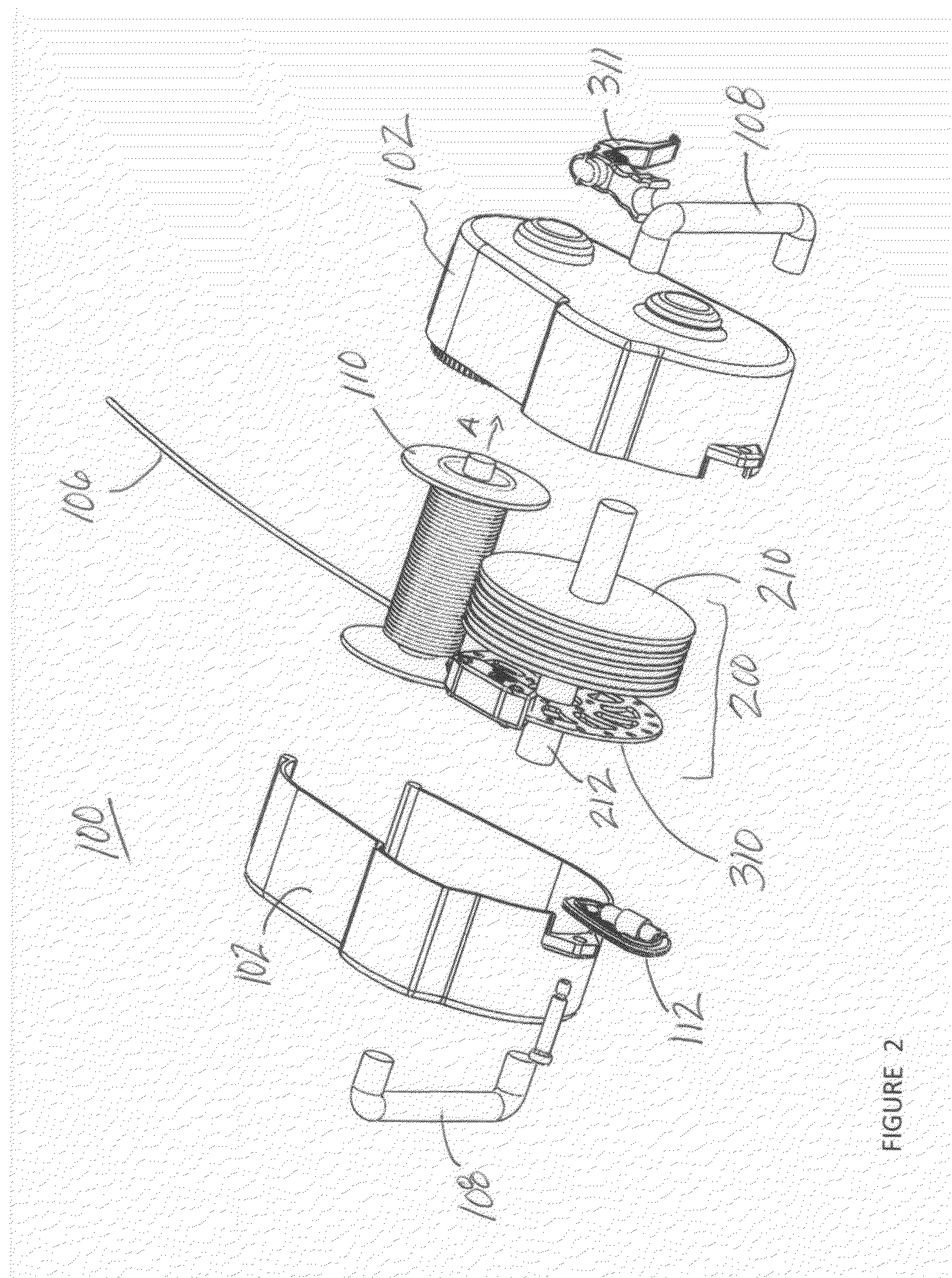
[0038]The present invention is a personal escape device that allows a person, animal, or inanimate object to be lowered in a controlled or controllable manner from a high location. The device is designed for a relatively low-cost, small size which may be used by payloads of variable weights.

[0039]An embodiment of the personal escape device of the present invention is illustrated in FIG. 1. As shown, the personal escape device 100 includes a housing or casing 102 manufactured from substantially rigid, formable or moldable materials, such as fiberglass, plastics, rigid metals, or other materials generally commercially available. The housing material should be of sufficient strength to withstand both force applied by the weight of the payload during deployment, and by the friction of the cord as it is deployed.

[0040]As described below, a primary spool 110, rotatable about a central axis A, is disposed within the housing 102, although not shown in FIG. 1. A cord 106 is wound around spoo...


PUM


Abstract

The invention presents devices for controlled descent from buildings. Such a device includes a housing having a primary spool about which a cord is wound, a payload coupler for attaching a harness assembly to the housing, and an unwind control assembly for controlling the rate of exit of the cord from the housing. An inventive device kit may include a convertible storage unit used to protectively store a device and which, upon deployment, may be used as a protective helmet. In using an inventive device, a user attaches the device to a fixture in a building, dons a harness and the converted helmet, attaches the device to the harness, and exits the building from a window or roof.

Description

CLAIM OF PRIORITY[0001]This application claims priority to U.S. provisional application Ser. No. 60 / 950,451, filed Jul. 18, 2007, incorporated herein fully by reference.FIELD OF THE INVENTION[0002]The present invention relates to emergency equipment and personal safety devices involving exiting a tall building in event of an emergency.BACKGROUND[0003]Each year, an estimated ten thousand fires occur in buildings that are seven stories or higher. Hundreds of firefighters and police risk their life every day by entering burning buildings to save trapped civilians. Additionally, terrorism, hostage situations, and violent crime rampages worldwide are increasing, often leaving people trapped high above the streets, waiting for rescue.[0004]An estimated 2,726 people died on Sep. 11, 2001, at the World Trade Center in New York City. Of that number, 343 were firemen who entered the building to save lives. An estimated 200 people were trapped civilians who willingly jumped from the buildings ...

Claims


Application Information

Patent Timeline
Patent Type & Authority Patents(United States)
IPC IPC(8): A62B1/10
CPCA62B1/10
Inventor STRASSER, MICHAELKING, THOMASSTONE, KEVIN R.
Owner STONES THROW
Learn More