
Device for cleaning vehicle wheels

a technology for cleaning wheels and wheels, which is applied in the direction of cleaning machines, carpet cleaners, vehicles, etc., can solve the problems of limited practicality and limited effective range of such wheel-washing brushes, and achieve the effect of improving the cleaning effect and improving the coverage of the surface to be cleaned

Inactive Publication Date: 2013-11-05
WASHTEC HLDG
View PDF31 Cites 2 Cited by
  • Summary
  • Abstract
  • Description
  • Claims
  • Application Information

AI Technical Summary

Benefits of technology

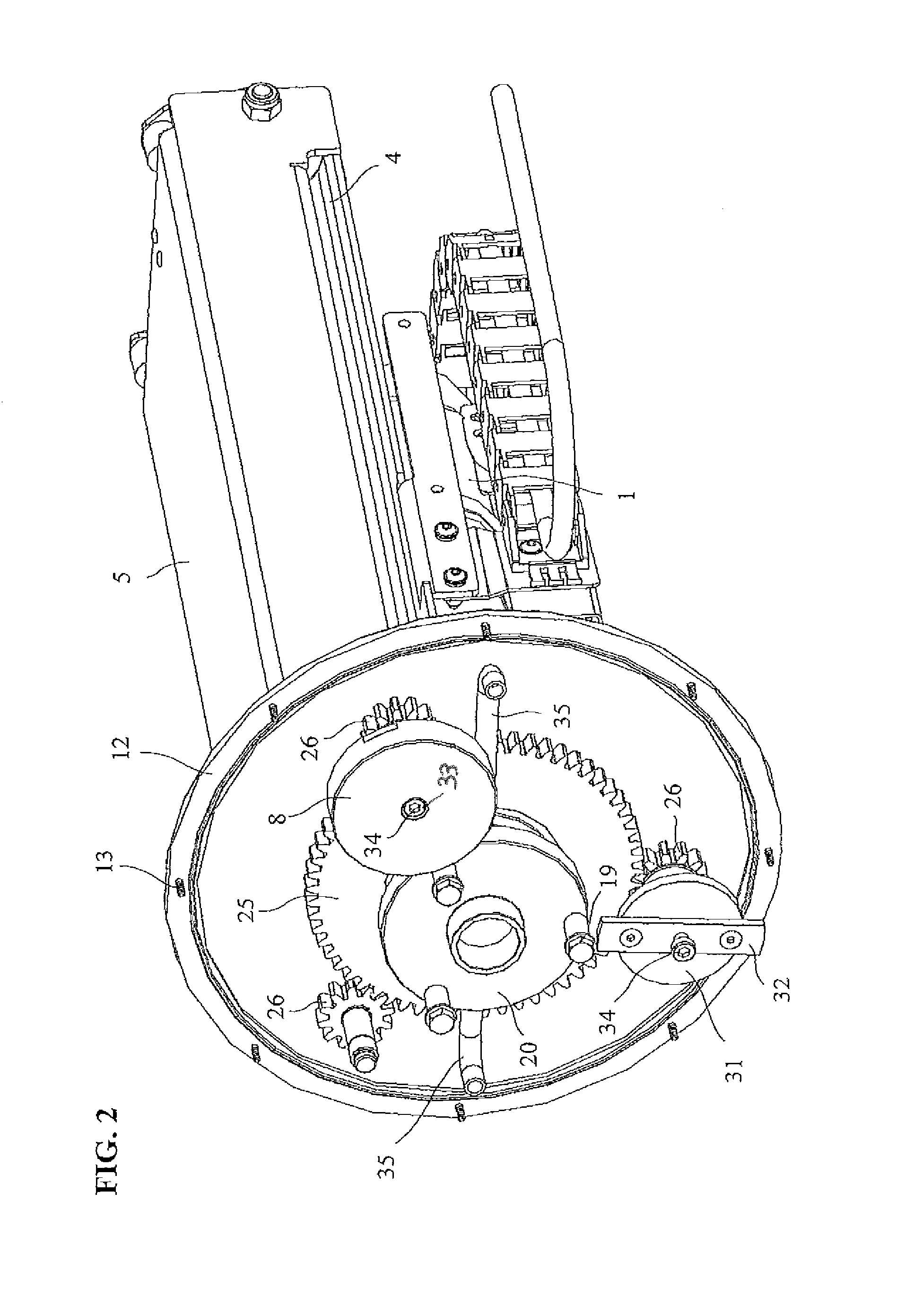
[0006]In the device according to the invention, the rotary body, driven by a drive motor about a central axis and equipped with cleaning elements such as a rim washing brush, comprises at least one rotary plate provided with additional cleaning elements, which is rotated by the rotation of the rotary body not only about the central axis but, via a gear unit, also about its own longitudinal axis. Within a rotary body constituting a main brush, it is possible in this manner, for example, for one or more inner brushes to be arranged that rotate at a speed corresponding to the drive motor on a circular path about the central axis of the rotary body, and additionally about their own axes at a different rotational speed. In this way an improved coverage of the surfaces to be cleaned, and thus an improved cleaning effect, is achievable.
[0007]One or more rotary plates with inner brushes or other cleaning elements can be arranged inside the rotary body. The mechanical coupling of the brushes has the effect that the outer brush carries out a rotation about the central axis and the inner brush or brushes carry out both a rotational movement about the central axis and a rotation about their own centers.
[0009]In a particularly expedient embodiment, the rotary disks can likewise be rotated by the drive motor via a transmission gear unit embodied as a planetary gear assembly, for example. The rotary disks can be driven by the transmission gear unit at a speed different from that of the rotary body, whereby an improved cleaning effect results. The several rotary plates with the cleaning elements, preferably in the form of brushes, arranged thereon need not have the same rotational speed either, i.e., both the diameter and the rotational speed can be different, which leads to favorable overlapping effects for rim washing.

Problems solved by technology

The movement possibilities for such wheel-washing brushes are limited, however, so that their effective range is correspondingly limited.

Method used


Image

  • Device for cleaning vehicle wheels
  • Device for cleaning vehicle wheels
  • Device for cleaning vehicle wheels

Examples


Embodiment Construction

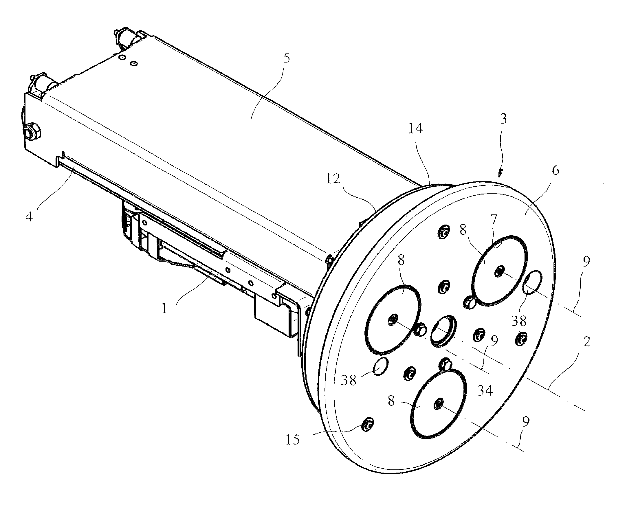
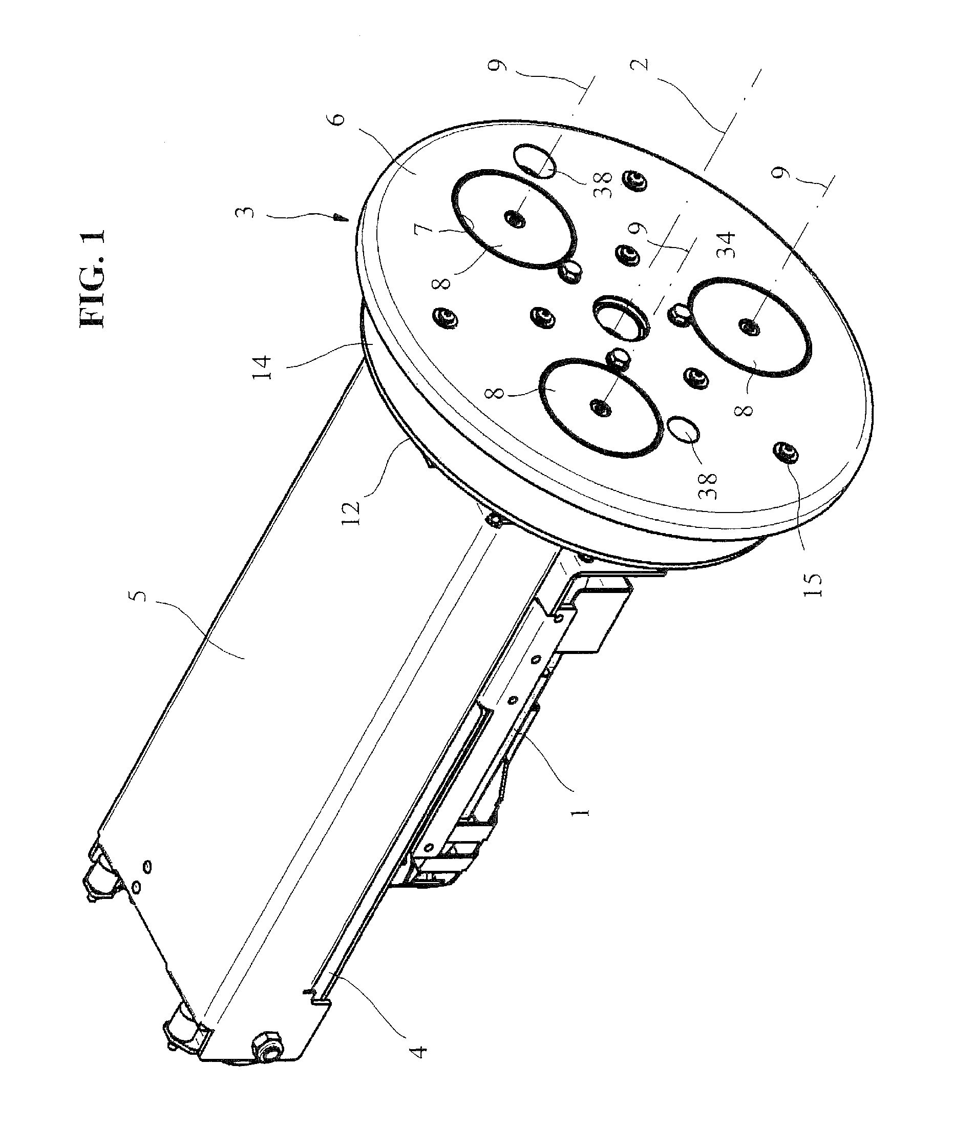
[0020]FIGS. 1-4 and FIGS. 6-7 show different views of a first embodiment of a base body 3, rotatable by means of a drive motor 1 about a center axis 2, for a device for cleaning vehicle wheels in a vehicle washing system. The device shown contains a carriage 5 movably guided via linear guides 4, on which the disk-shaped base body 3, adapted to the size of the vehicle wheel rims, can be moved by a linear drive, not shown, between a retracted rest position and an advanced cleaning position.

[0021]As is evident from FIG. 1, the base body 3, constructed here in several parts, has three circular openings 7 with rotary disks 8 arranged therein in a front end plate 6. The rotary disks 8 in the illustrated embodiment are spaced at equal angles on a circle concentric with the central axis 2 and are rotated by the rotation of the base body 3 by means of the drive motor 1, not only about the central axis 2 but also about their own longitudinal axes 9 via a gear assembly to be described in detai...


PUM


Abstract

The invention relates to a device for cleaning vehicle wheels that contains a rotary body driven rotationally by a drive motor about a central axis, with cleaning elements arranged on its front end face. An improved cleaning can be achieved by virtue of the fact that the rotary body contains at least one rotary plate equipped with additional cleaning elements that is rotated by the rotation of the rotary body, not only about the central axis but also, via a gear assembly, about its own longitudinal axis.

Description

CROSS REFERENCE TO RELATED APPLICATIONS[0001]This application claims priority under 35 U.S.C. §119 to German Patent Application No. 10 2009 037 772.7 filed Aug. 17, 2009, the entire contents of which are incorportated herein by reference.FIELD OF THE INVENTION[0002]The invention relates to a device for cleaning vehicle wheels.BACKGROUND OF THE INVENTION[0003]Previously known devices for cleaning vehicle wheels generally have a wheel-washing brush configured as a plate brush that contains a brush body driven rotationally with the aid of a drive motor and that has cleaning brushes arranged on its end face for contact with a vehicle wheel. The movement possibilities for such wheel-washing brushes are limited, however, so that their effective range is correspondingly limited.[0004]The problem of the invention is to create a device of the type mentioned above that allows an improved cleaning of the vehicle wheels.[0005]This problem is solved by the device described herein. Expedient conf...

Claims


Application Information

Patent Timeline
Patent Type & Authority Patents(United States)
IPC IPC(8): B60S3/06
CPCB60S3/042
Inventor KEUSCH, SIEGFRIED
Owner WASHTEC HLDG
Learn More