Mower with thumb wheel throttle control

a technology of throttle control and mower, which is applied in the field of throttle control used on mowers, can solve the problems of holding the operator and impairing the steering control of the operator

Inactive Publication Date: 2013-11-05
TORO CO THE
View PDF26 Cites 16 Cited by
  • Summary
  • Abstract
  • Description
  • Claims
  • Application Information

AI Technical Summary

Problems solved by technology

Accordingly, fitting a pivotal throttle lever onto the control panel is often a challenge for the mower designer.
This at least temporarily decreases the hold the operator has on the handle assembly thereby potentially impairing the steering control the operator is able to exert on the mower using the handle assembly.

Method used


Image

  • Mower with thumb wheel throttle control
  • Mower with thumb wheel throttle control
  • Mower with thumb wheel throttle control

Examples


Embodiment Construction

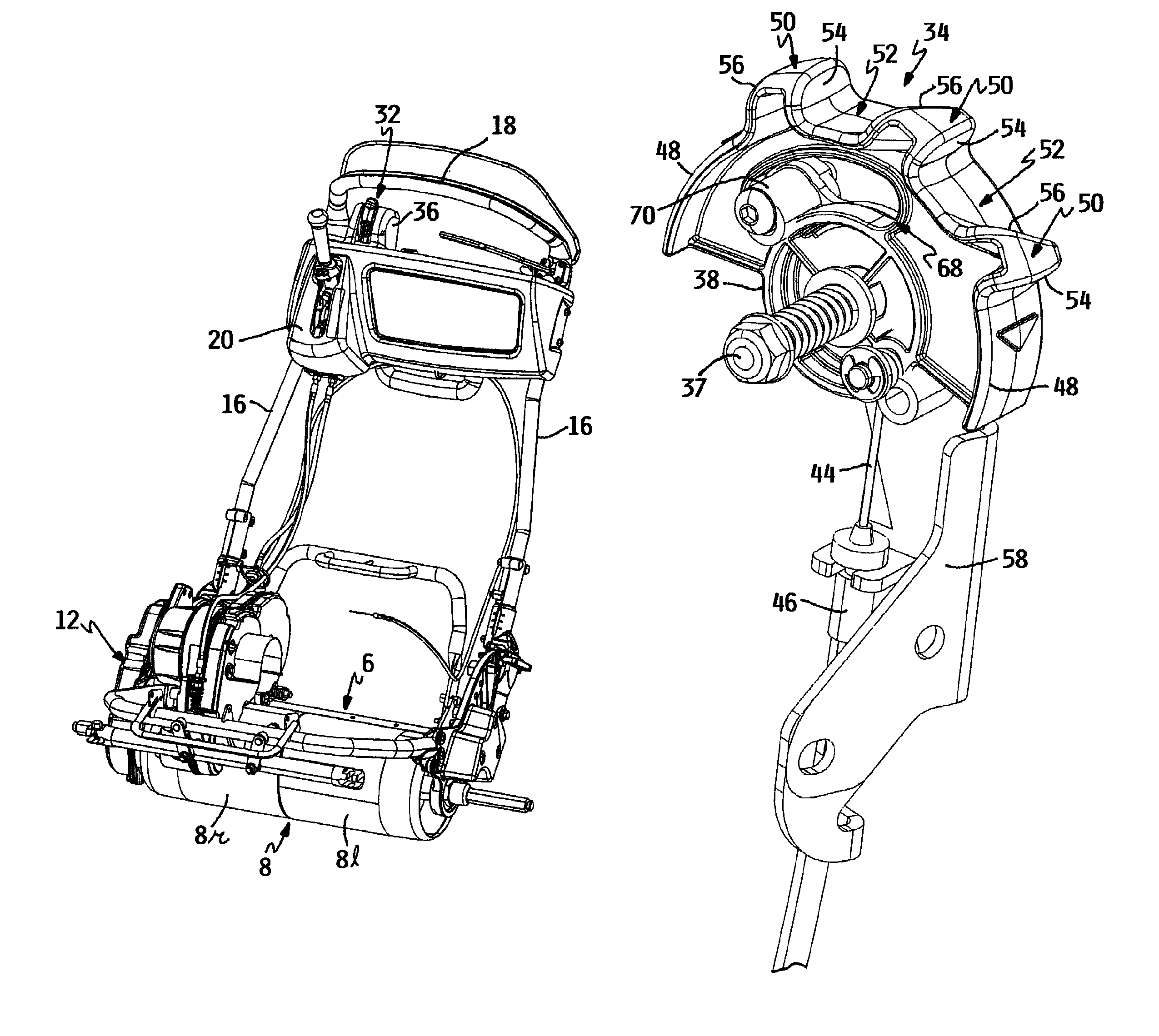
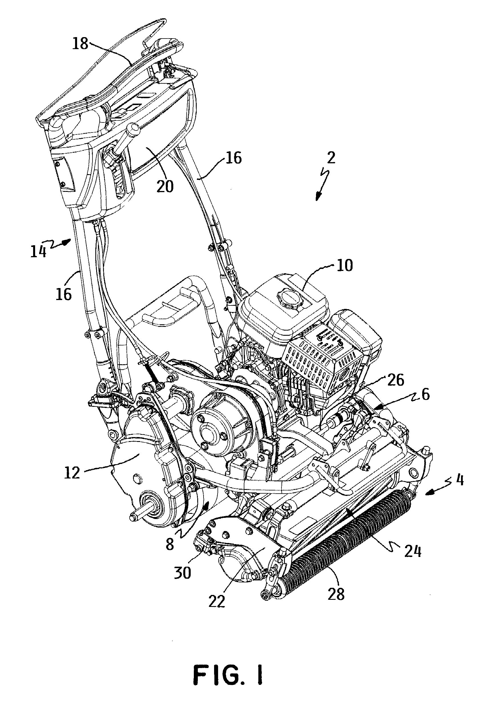
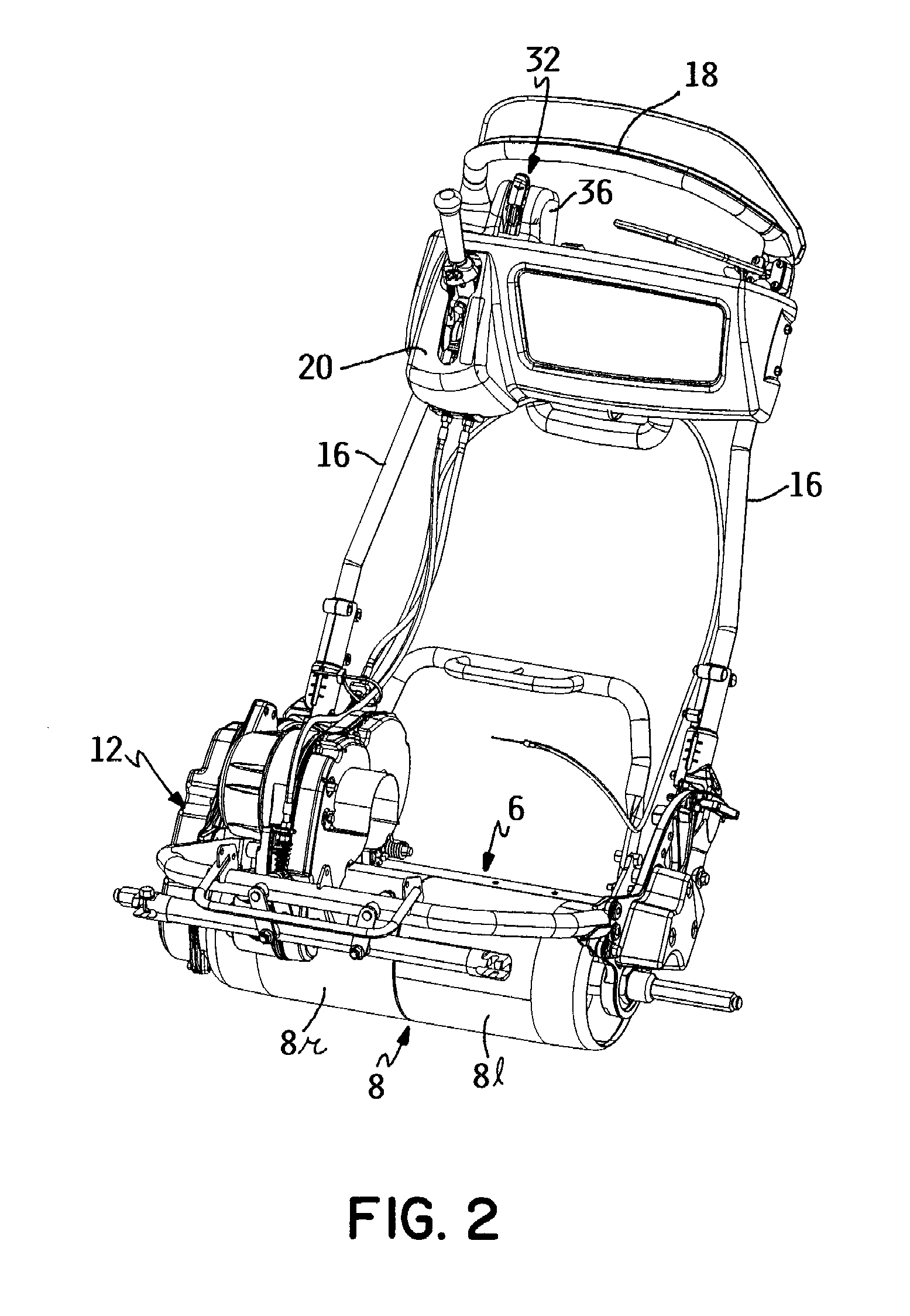
[0017]A mower according to this invention is generally illustrated as 2 in FIG. 1. Mower 2 preferably comprises a walk greensmower having a reel cutting unit 4 for precision mowing of grass at low heights of cut on golf course greens or the like. However, mower 2 is not limited to being a greensmower or even a reel mower but may comprise mowers of other types. For example, mower 2 could comprise a rotary mower having one or more grass cutting blades that rotate about vertical axes in horizontal cutting planes.

[0018]Referring to both FIGS. 1 and 2, mower2 comprises a traction frame 6 that is supported by a ground engaging traction drum 8 which is split into separate left and right drum halves 8l and 8r. Traction frame 6 mounts a power source comprising an internal combustion engine 10. Engine 10 is operatively coupled to traction drum 8 through a traction drive system 12 for rotating traction drum 8 when engine 10 is operating to self-propel mower 2 over the ground. Traction drive sy...


PUM


Abstract

A mower for cutting grass comprises a traction frame that is self-propelled over the ground by a power source carried on the traction frame. The mower includes a thumb wheel throttle control that progressively increases and decreases the power output of the power source as the thumb wheel is rotated in one direction or an opposite direction. The thumb wheel has a plurality of tabs that define grooves on an arcuate rim on the thumb wheel for receiving a thumb or index finger of one of the operator's hands.

Description

TECHNICAL FIELD[0001]This invention relates to mowers for cutting grass and, more particularly, to a throttle control used on a mower for varying the power output of a power source carried on the mower.BACKGROUND OF THE INVENTION[0002]Walk reel mowers are known for the precision cutting of grass to very low heights of cut. Such mowers are most commonly used for cutting the grass on the greens of golf courses and thus are typically referred to as greensmowers. The mower includes a reel cutting unit having a rotatable reel that sweeps the grass against a sharpened bedknife for cutting the grass between the blades of the reel and the bedknife. The mower is self-propelled by a power source carried on the mower which is operatively connected to a rotatable, ground engaging traction drum carried on the mower.[0003]The walk reel mower described above includes a generally U-shaped handle assembly that extends upwardly and rearwardly therefrom to allow an operator who walks on the ground beh...

Claims


Application Information

Patent Timeline
Patent Type & Authority Patents(United States)
IPC IPC(8): A01D69/06
CPCA01D34/62A01D34/47
Inventor SCHMIDT, GORDON R.ULLRICH, HELMUT J.
Owner TORO CO THE
Why Eureka
Try Eureka