
Photoelectric converter providing a waveguide along the surface of the mount substrate

a technology of waveguide and mount substrate, which is applied in the field of photoelectric converters, can solve the problems of significantly suppressing the device height, and achieve the effect of reducing the device height and low device heigh

Active Publication Date: 2013-11-05
PANASONIC CORP
View PDF39 Cites 32 Cited by
  • Summary
  • Abstract
  • Description
  • Claims
  • Application Information

AI Technical Summary

Benefits of technology

The present invention provides a photoelectric converter that can reduce the device height. By using a waveguide along the surface of the mount substrate, the device's overall thickness can be suppressed, resulting in a low height. This solution helps to minimize the space needed for the device, which is useful in various applications.

Problems solved by technology

However, even in this manner, the device height at least corresponding to the size of the light emitting element and a control IC element is necessary, and hence it is not possible to significantly suppress the device height.Patent Document 1: Japanese Patent Laid-Open No. 2001-42170

Method used


Image

  • Photoelectric converter providing a waveguide along the surface of the mount substrate
  • Photoelectric converter providing a waveguide along the surface of the mount substrate
  • Photoelectric converter providing a waveguide along the surface of the mount substrate

Examples


Embodiment Construction

[0060]In the following, the best mode for carrying out the present invention is described with reference to accompanying drawings.

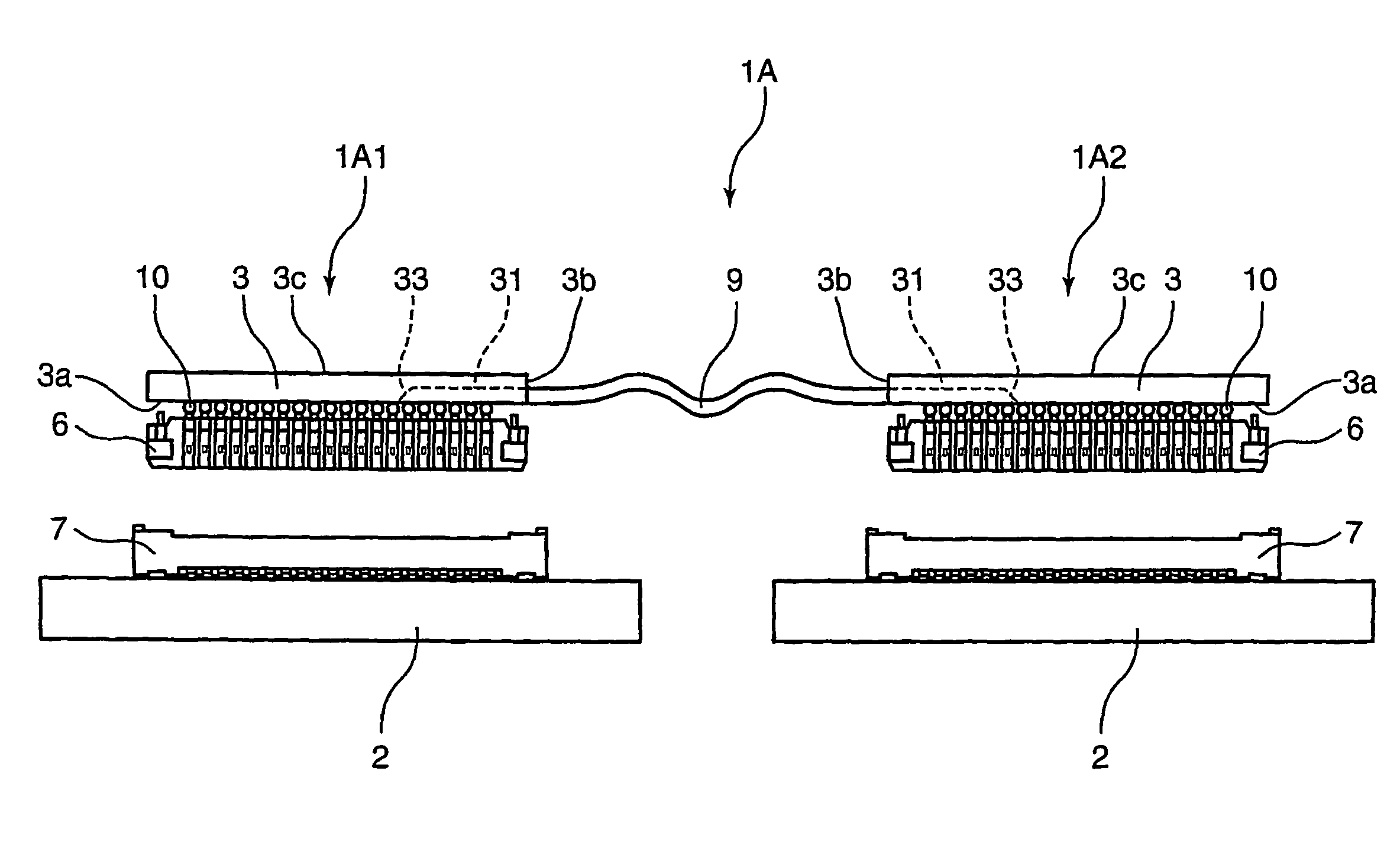
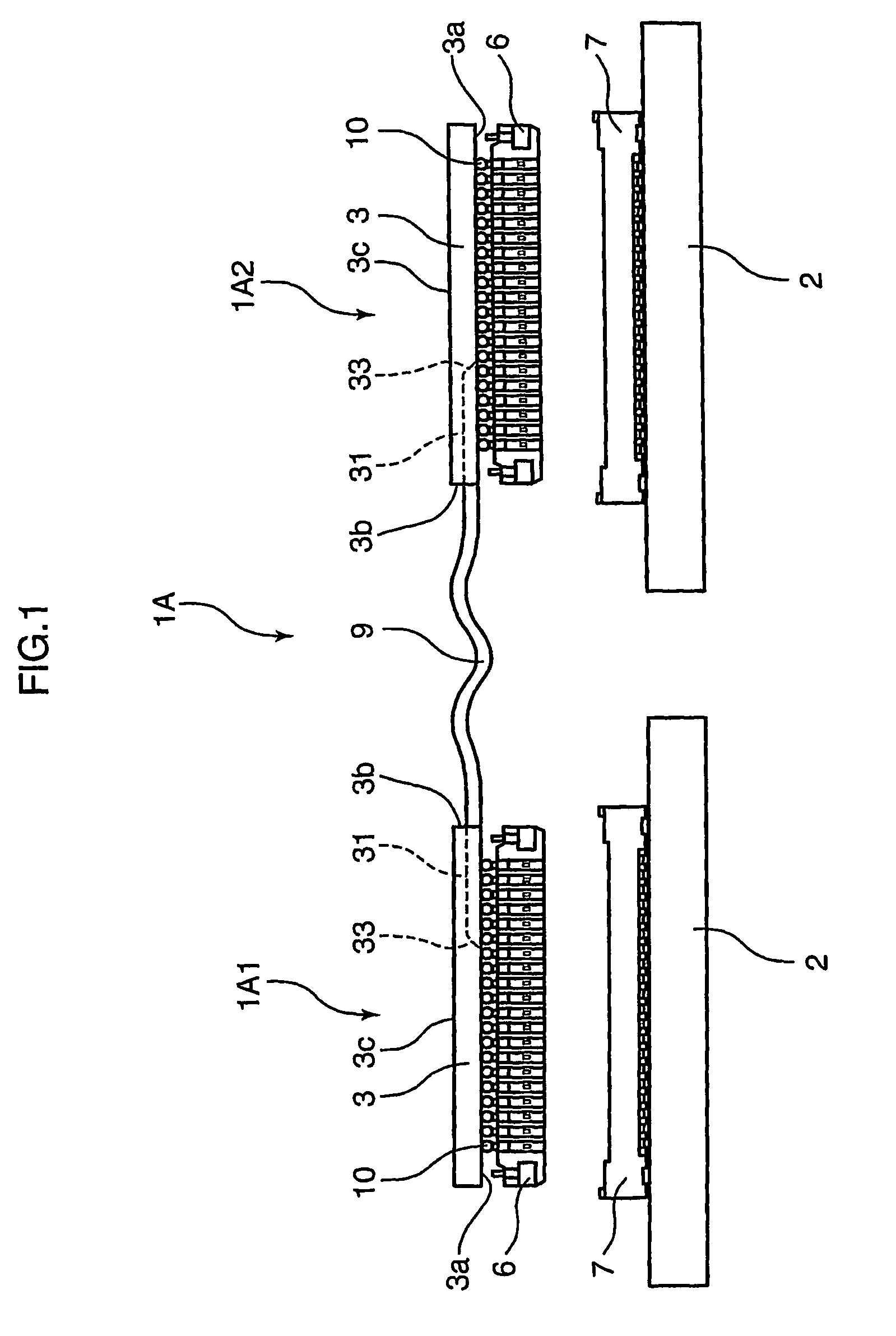
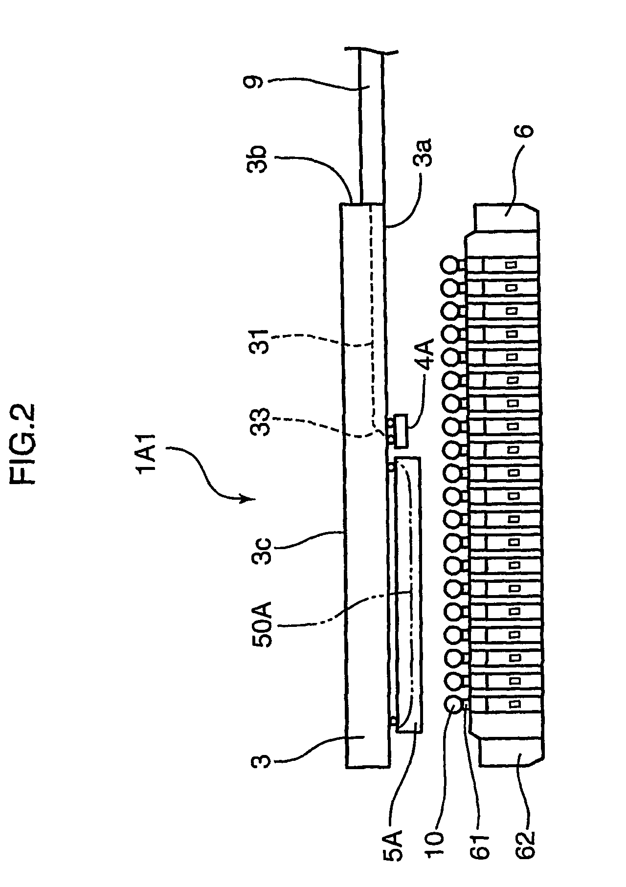
[0061]FIG. 1 shows a photoelectric converter 1A according to a first embodiment of the present invention. The photoelectric converter 1A includes a light emitting side photoelectric converting portion (also referred to as E / O module) 1A1 adapted to be mounted on a wiring substrate 2 by engagement of a header (electric connector) 6 and a socket (electric connector) 7, a light receiving side photoelectric converting portion (also referred to as O / E module) 1A2 adapted to be mounted by engagement of the electric connectors 6 and 7 similarly to the other wiring substrate 2, and an external waveguide 9 adapted to effect an optical coupling between the converting portions 1A1 and 1A2. That is, in the photoelectric converter 1A, the electric converting portion on the other side seen from the light emitting side photoelectric converting portion 1A1 or the light r...


PUM


Abstract

To provide a photoelectric converter capable of reducing the height of the device. The photoelectric converter includes: a light emitting element or a light receiving element; an IC circuit for transmitting / receiving an electric signal to / from the light emitting element or the light receiving element; a mount substrate adapted to be mounted on one surface from the side on which the light emitting element emits light, or the side on which the light receiving element receives light; an electric connector adapted to be provided on the one surface or the other surface of the mount substrate, and to be attached and detached to and from an external connector; and a waveguide adapted to be provided on the mount substrate along the one surface or the other surface of the mount substrate, and to be optically coupled to the light emitting element or the light receiving element.

Description

TECHNICAL FIELD[0001]The present invention relates to a photoelectric converter provided with an optical element.BACKGROUND ART[0002]Conventionally, as a photoelectric converter, as described in, for example, FIG. 9 of Patent Document 1, there is known a type including: a light emitting element which emits light by converting an electric signal into an optical signal; a substrate on which an IC circuit for transmitting an electric signal to the light emitting element is formed and the light emitting element is mounted on one surface from the side opposite to the light emitting side of the light emitting element: and a waveguide which is arranged to extend from the light emitting element in the direction perpendicular to the one surface of the substrate and transmits the light emitted by the light emitting element. Note that in place of the light emitting element, it is also possible to use a light receiving element which receives light and converts the received optical signal to an ...

Claims


Application Information

Patent Timeline
Patent Type & Authority Patents(United States)
IPC IPC(8): G01J1/42
CPCG02B6/4201G02B6/4214G02B6/4232G02B6/43G02B2006/12147G02B6/4284H01L2224/16225G02B6/10G02B6/42
Inventor ASAHI, NOBUYUKINISHIMURA, MAKOTOYAGYU, HIROYUKIKINUGASA, YUTAKAMATSUMOTO, TAKUYA
Owner PANASONIC CORP
Learn More