Driver circuit for powering a DC lamp in a non-DC lamp fitting

a technology for driving circuits and dc lamps, which is applied in the direction of fixed installation, lighting and heating apparatus, instruments, etc., can solve the problems of time-consuming and expensive rewiring of lighting circuits, low input power factor and power density, and low energy efficiency

Active Publication Date: 2013-11-05
CITY UNIVERSITY OF HONG KONG
View PDF9 Cites 15 Cited by
  • Summary
  • Abstract
  • Description
  • Claims
  • Application Information

AI Technical Summary

Benefits of technology

[0005]An object of the invention is to mitigate or obviate to some degree one or more problems associated with known lamp fittings designed for non-dc or non-LED type lamps.
[0009]The driver circuit can be powered by different power sources such as an ac mains power supply, a low-frequency electromagnetic ballast, or a high-frequency electronic ballast. Its input impedance is controlled to meet the operational requirements and conditions of the different power sources and its output is controlled to deliver the required power to the LED lamp / array. When the driver circuit is powered by the ac mains or a low-frequency electromagnetic ballast, it is configured as an active power factor correction circuit. Its input current is controlled to follow the wave shape of the source voltage. When the driver circuit is powered by a high-frequency electronic ballast, it is configured as a phase-shifted resonant converter circuit with controllable input resistance and susceptance. The driver circuit having such universal compatibility with available ac power sources allows replacement of fluorescent lamps with the retrofit dc or LED lamps without removal or replacement of existing ballasts or modification of the lighting infrastructure.
[0011]One unexpected technical benefit of the driver circuit according to the invention is that, where the driver circuit is operating to power a dc lamp with an existing ballast in an existing non-dc lamp fitting and the ballast then fails, the driver circuit can enable the dc lamp to still operate directly with the lamp fitting's ac power supply rather than through the ballast thereby negating the need to repair or replace the ballast.
[0014]Preferably also, the second stage is configured to operate as a power factor correction circuit when in its low frequency made of operation and the filter circuit operates as a low pass filter to reduce or eliminate high-frequency harmonics generated by the second stage operating as a power factor correction circuit. The second stage may be configured to operate as a bridgeless power factor correction circuit in discontinuous conduction mode when in its low frequency made of operation. The power factor correction circuit may be operated in its discontinuous conduction mode with a fixed switching frequency.

Problems solved by technology

However, their energy efficiency, input power factor and power density are typically low.
However, even though the existing fluorescent lamp fixtures / fittings could be retained, the ballasts (electromagnetic or electronic) installed inside such lamp fixtures would have to be removed or replaced by LED drivers.
This requires rewiring of the lighting circuits which is time consuming and expensive, particularly as it has to be performed in situ with the existing fittings and fixtures.

Method used


Image

  • Driver circuit for powering a DC lamp in a non-DC lamp fitting
  • Driver circuit for powering a DC lamp in a non-DC lamp fitting
  • Driver circuit for powering a DC lamp in a non-DC lamp fitting

Examples


Embodiment Construction

[0042]The following description is of a preferred embodiment by way of example only and without limitation to the combination of features necessary for carrying the invention into effect.

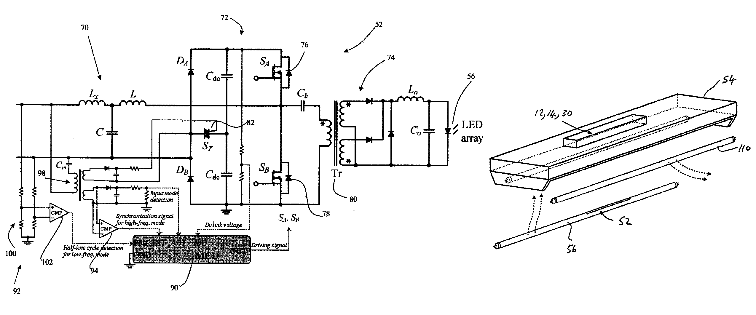
[0043]The present invention provides a driver circuit for a dc lamp that enables said dc lamp to work in existing lamp fittings for non-dc powered lamps without changing or modifying the existing lighting fixtures or infrastructure. The driver circuit adapts a dc lamp such as an LED lamp or an LED lamp array to be used in a non-dc or non-LED type lamp fitting without modification of the lamp fitting. The driver circuit is such that the LED lamp or LED lamp array can be inserted into the non-LED type lamp fitting as a replacement for anon-LED lamp such that the LED lamp and the driver circuit are retained in the lamp fitting and make electrical connections with the lamp fitting's electrical contacts for powering the inserted lamp. The driver circuit enables the LED lamp or lamp array to operate with ...


PUM


Abstract

A driver circuit for adapting an LED lamp or an LED lamp array to be used in a lamp fitting for a non-LED type lamp without modification of the lamp fitting. The LED lamp or LED lamp array can be inserted into the lamp fitting as a replacement for a non-LED lamp. The driver circuit has a first stage with a filter circuit and having an input connectable to any of an ac power supply, an electromagnetic ballast or an electronic ballast of the lamp fitting; a second stage with a high frequency switched network and having an input connected to an output of the first stage; and a third stage with an ac / dc converter and having an input connected to an output of the second stage and an output connectable to an LED lamp. The third stage is configured to deliver dc power to a connected LED lamp. The second stage is configured to operate in a low frequency mode and in a high frequency mode.

Description

FIELD OF THE INVENTION[0001]The invention relates to a driver circuit for powering a dc lamp such as a Light Emitting Diode (LED) lamp in a non-dc powered lamp fitting and, more particularly, to a driver circuit for enabling an LED lamp or LED lamp array to be used in a lamp fitting designed for a non-LED type lamp.BACKGROUND OF THE INVENTION[0002]Fluorescent lamps have been widely used in many residential, commercial and industrial lighting applications as they offer high efficacy (lumen per Watt) and have proven operational stability. As they require a high ignition voltage to discharge the lamp and have negative resistance, a device called a ballast is used to generate the ignition voltage and regulate the lamp current.[0003]Ballasts are of two major kinds: a low-frequency electromagnetic type and a high-frequency electronic type. Electromagnetic ballasts are made of passive components. They have the advantages of high reliability, long lifetime, and robustness against transient ...

Claims


Application Information

Patent Timeline
Patent Type & Authority Patents(United States)
IPC IPC(8): H05B37/03
CPCH05B33/0818Y02B20/346Y02B20/383Y02B20/30H05B45/3725H05B45/39
Inventor CHUNG, SHU HUNG HENRYCHEN, NAN
Owner CITY UNIVERSITY OF HONG KONG
Why Eureka
Try Eureka