Method and apparatus for special end area inspection

a tubular member and end area technology, applied in the direction of magnetisation measurement, instruments, material magnetic variables, etc., can solve the problems of end flux leakage, deviation of magnetic field, unusable residual magnetization of tubular members, etc., to prevent damage to the end area and the inspection apparatus.

Active Publication Date: 2013-11-05
OILPATCH TECH
View PDF27 Cites 13 Cited by
  • Summary
  • Abstract
  • Description
  • Claims
  • Application Information

AI Technical Summary

Benefits of technology

[0011]An advantage of the disclosed embodiments is that they provide a magnetic inspection assembly that may inspect the ends of a tubular member or a tubular coupler. In addition, the disclosed embodiments provide an inspection apparatus that does not leave the tubular member or coupler magnetized fol

Problems solved by technology

This process may cause an undesirable residual magnetization of the tubular member.
When inspecting the end areas of tubular members or short coupler tubular members, the short length of the end or

Method used


Image

  • Method and apparatus for special end area inspection
  • Method and apparatus for special end area inspection
  • Method and apparatus for special end area inspection

Examples


Embodiment Construction

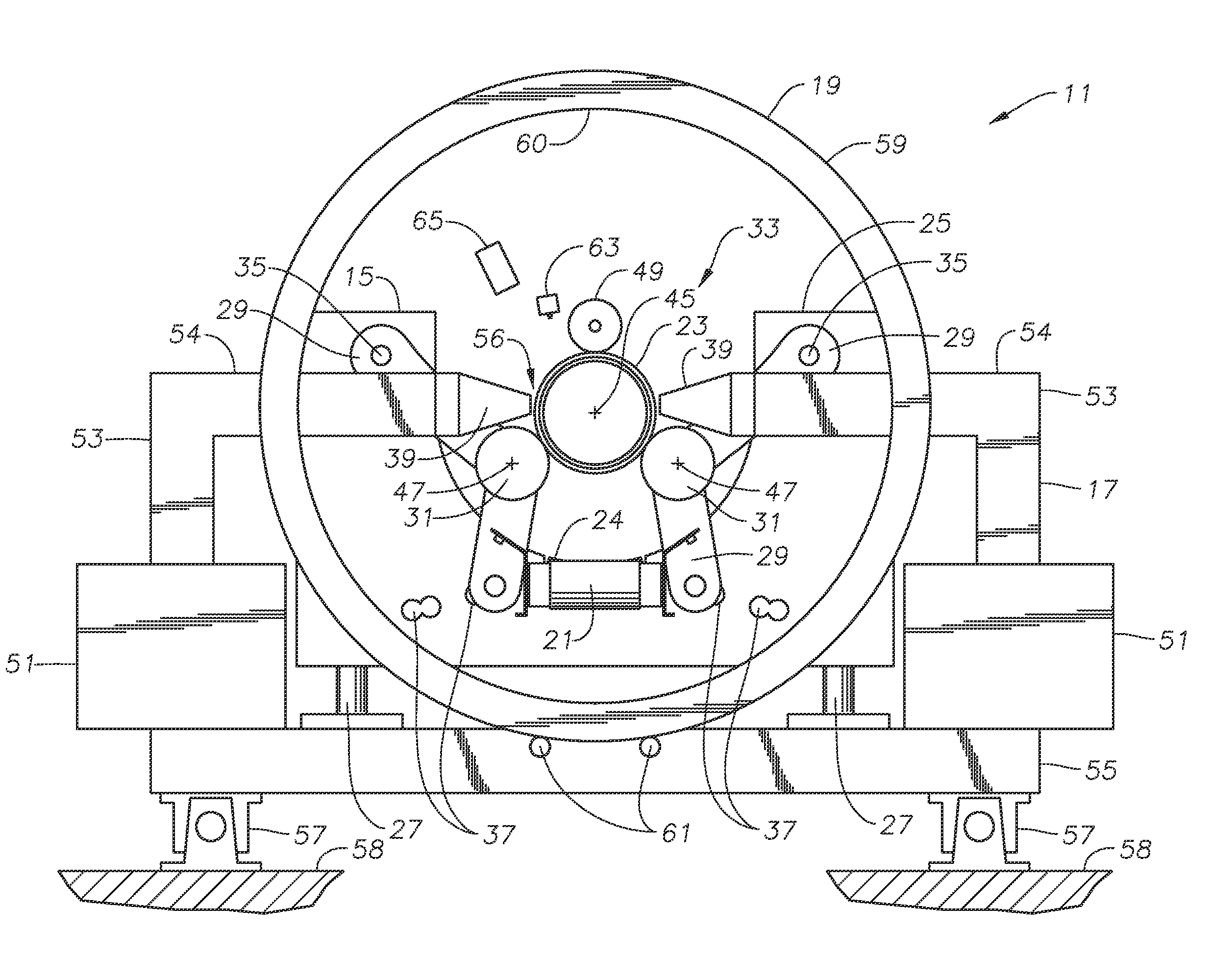
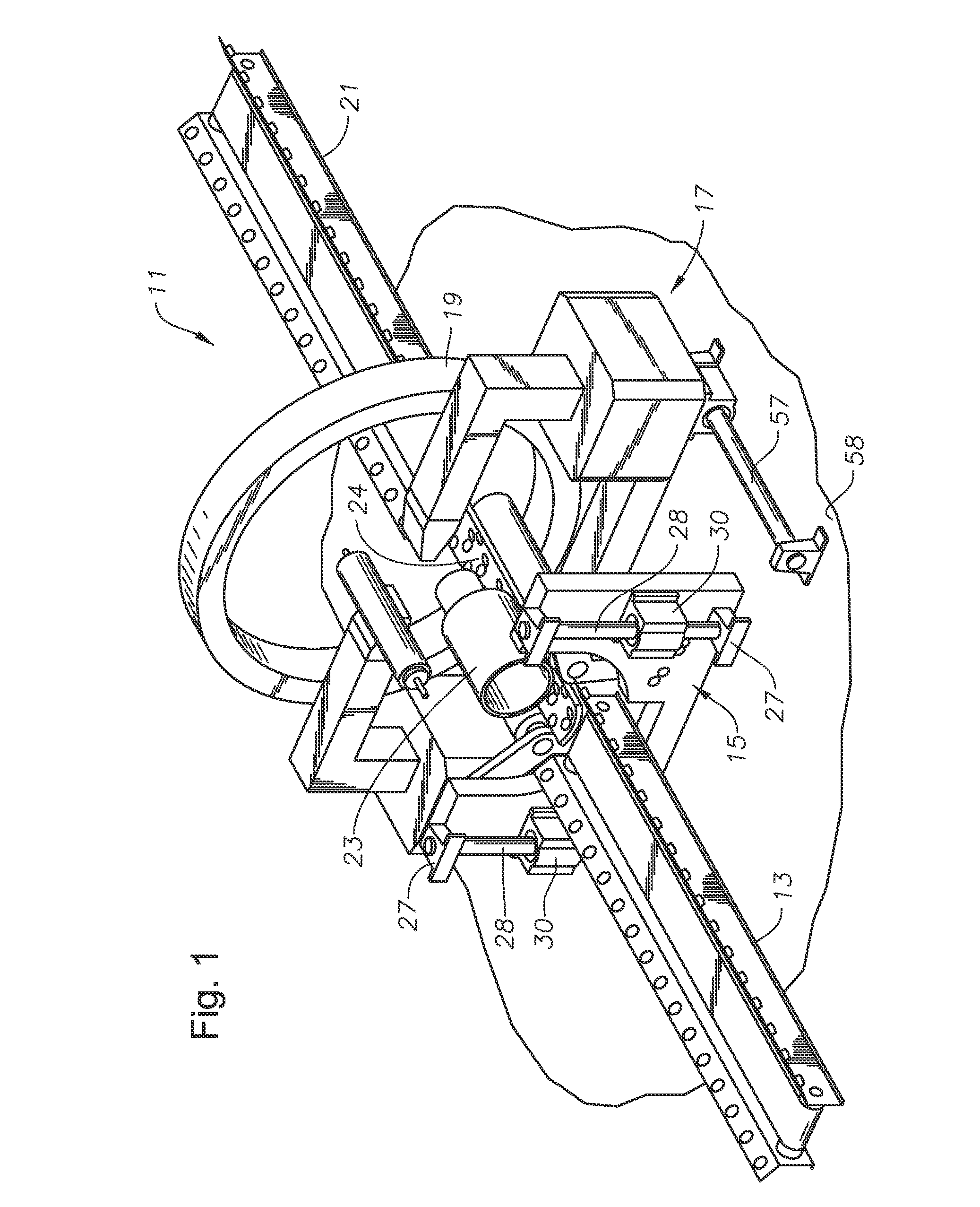
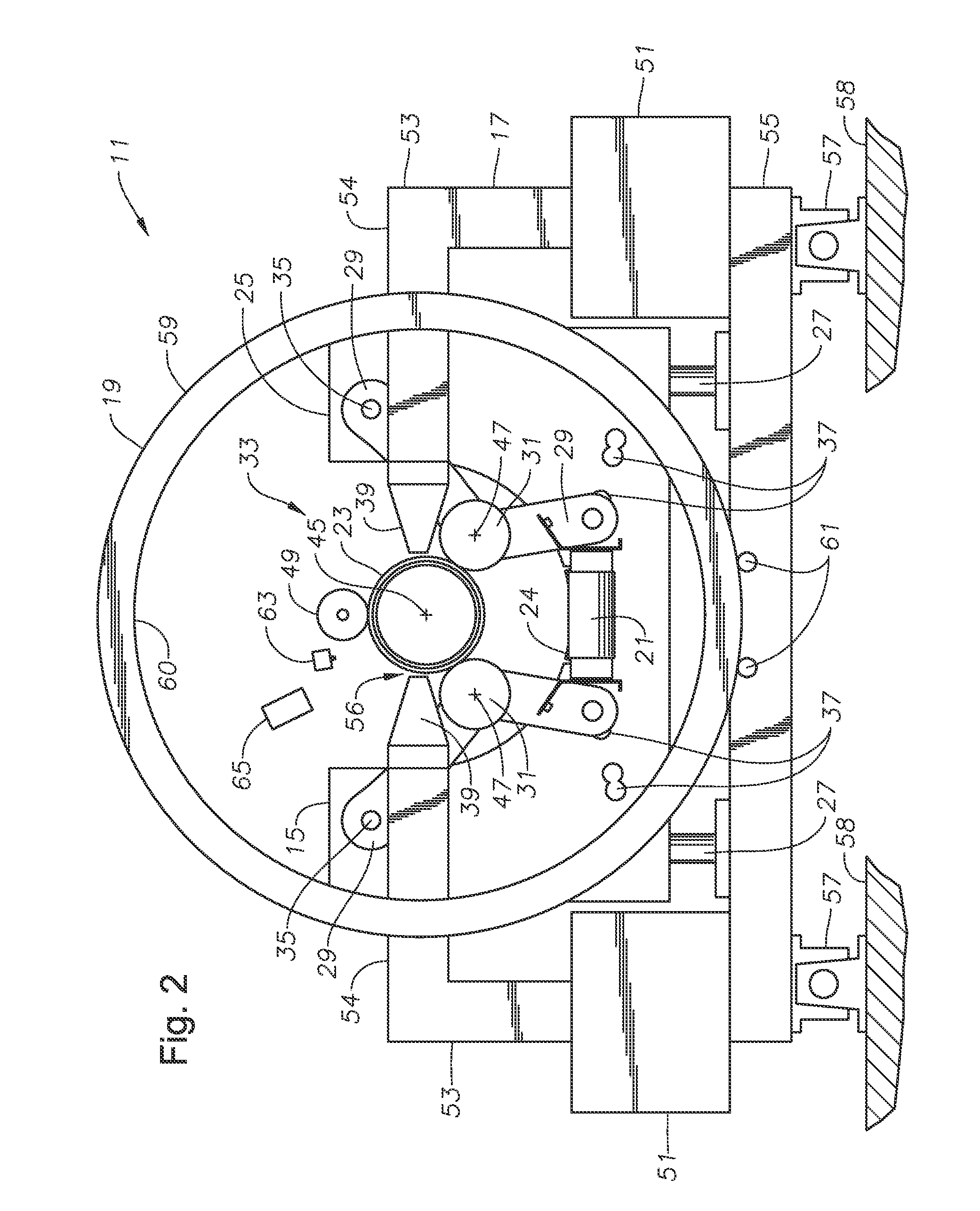
[0030]The present invention will now be described more fully hereinafter with reference to the accompanying drawings which illustrate embodiments of the invention. This invention may, however, be embodied in many different forms and should not be construed as limited to the illustrated embodiments set forth herein. Rather, these embodiments are provided so that this disclosure will be thorough, complete, and will fully convey the scope of the invention to those skilled in the art. Like numbers refer to like elements throughout, and the prime notation, if used, indicates similar elements in alternative embodiments.

[0031]In the following discussion, numerous specific details are set forth to provide a thorough understanding of the present invention. However, it will be obvious to those skilled in the art that the present invention may be practiced without such specific details. Additionally, for the most part, details concerning power controls, station structural framework, and the li...


PUM


Abstract

A magnetic inspection station for tubular members and methods for operating the same have a longitudinal flaw detection assembly adapted to pass a circumferential magnetic field through a tubular member and a transverse flaw detection assembly adapted to pass a longitudinal magnetic field through the tubular member. The magnetic fields cause congregation of a ferromagnetic particles sprayed on the tubular member in a magnetic particle inspection fluid. The congregation of ferromagnetic particles indicates a flaw in the tubular member. The magnetic inspection station includes a clamping apparatus positioned closely adjacent to the magnetic inspection station and adapted to support the tubular member within the magnetic inspection station and exert a compensating force on the tubular member to resist the magnetic forces generated by the longitudinal flaw detection assembly and the transverse flaw detection assembly.

Description

[0001]This application claims priority to and the benefit of U.S. Provisional Application No. 61 / 460,785, filed on Jan. 7, 2011, entitled “Method and Apparatus for Special End Area Inspection” to Carroll Roy Thompson which application is hereby incorporated in its entirety herein by reference.BACKGROUND OF THE INVENTION[0002]1. Field of the Invention[0003]The present invention relates in general to a method and apparatus for inspecting tubular members and, in particular, to an apparatus and method for inspecting tubular couplers and tubular member ends.[0004]2. Brief Description of Related Art[0005]Tubular members are often inspected by passing magnetic fields through the tubular member. Where a flaw is found in a wall of the tubular member, the magnetic field will deviate causing magnetic flux to leak from the surface of the tubular member. A suspension containing ferromagnetic particles visible to the human eye under appropriate conditions is sprayed on the tubular member while th...

Claims


Application Information

Patent Timeline
IPC IPC(8): G01R33/12G01N27/84G01N27/82G01N27/72
CPCG01R33/12G01N27/72G01N27/82G01N27/84G01R33/0213G01R33/1215
Inventor THOMPSON, CARROLL ROY
Owner OILPATCH TECH
Why Eureka
Try Eureka