Spatially combined waveforms for electrophoretic displays

a technology of electrophoretic display and combined waveforms, which is applied in the field of electrophoretic display, can solve the problems of inability to accurately measure the temperature of the medium, the optical response speed of the display device may not remain constant, and the performance of the display (e.g., grey level) may not remain the sam

Active Publication Date: 2013-11-05
E INK CORPORATION
View PDF99 Cites 90 Cited by
  • Summary
  • Abstract
  • Description
  • Claims
  • Application Information

AI Technical Summary

Problems solved by technology

However, the optical response speed of a display device may not remain constant because of temperature variation, batch variation, photo-exposure or, in some cases, due to aging of the display medium.
As a result, when driving waveforms with fixed durations are applied, the performance of the display (e.g., grey level) may not remain the same because the optical response speed of the display medium has changed.
However, the temperature sensor does not always accurately measure the temperature of the medium due to the thermal time constant.
In addition, this approach is costly because more memory is needed for the additional look-up tables in the system.
But such a system would add undesired complexity to the display device.

Method used


Image

  • Spatially combined waveforms for electrophoretic displays
  • Spatially combined waveforms for electrophoretic displays
  • Spatially combined waveforms for electrophoretic displays

Examples


Embodiment Construction

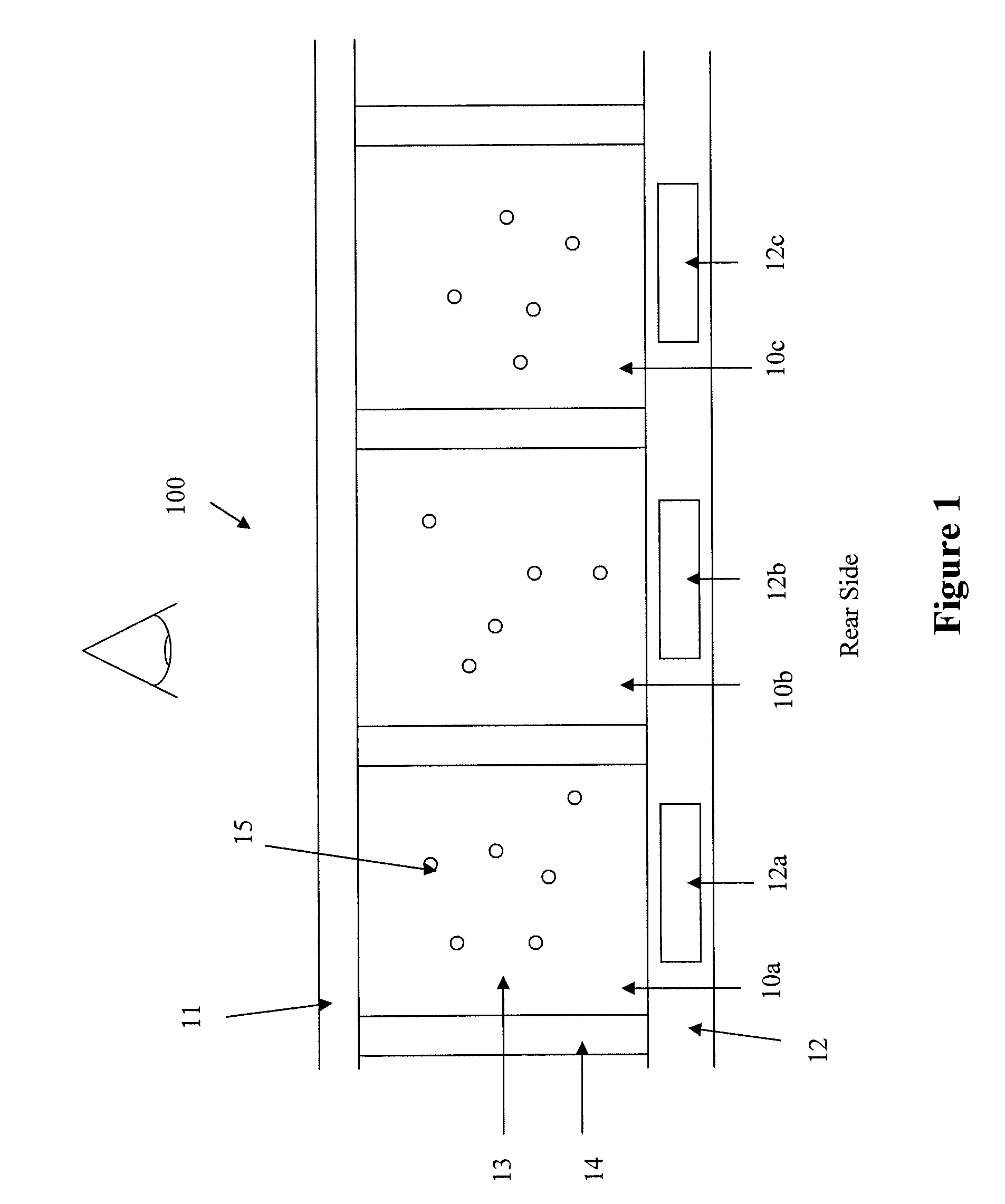
[0024]FIG. 1 illustrates an electrophoretic display (100) which may be driven by any of the driving methods presented herein. In FIG. 1, the electrophoretic display cells 10a, 10b, 10c, on the front viewing side indicated with a graphic eye, are provided with a common electrode 11 (which is usually transparent and therefore on the viewing side). On the opposing side (i.e., the rear side) of the electrophoretic display cells 10a, 10b and 10c, a substrate (12) includes discrete pixel electrodes 12a, 12b and 12c, respectively. Each of the pixel electrodes 12a, 12b and 12c defines an individual pixel of the electrophoretic display. However, in practice, a plurality of display cells (as a pixel) may be associated with one discrete pixel electrode.

[0025]It is also noted that the display device may be viewed from the rear side when the substrate 12 and the pixel electrodes are transparent.

[0026]An electrophoretic fluid 13 is filled in each of the electrophoretic display cells 10a, 10b and ...


PUM


Abstract

The present invention is directed to a driving method for compensating the response speed change of an electrophoretic display due to temperature variation, photo-degradation or aging of the display device, without a complex structure (e.g., use of sensors). This is accomplished by combining two waveforms, one of which causes the grey level to become dimmer and the other waveform causes the grey level to become brighter, as the response speed degrades.

Description

[0001]This application claims priority to U.S. Provisional Application No. 61 / 255,028, filed Oct. 26, 2009; the content of which is incorporated herein by reference in its entirety.FIELD OF THE INVENTION[0002]An electrophoretic display is a device based on the electrophoresis phenomenon of charged pigment particles dispersed in a solvent. The display usually comprises two electrode plates placed opposite of each other and a display medium comprising charged pigment particles dispersed in a solvent is sandwiched between the two electrode plates. When a voltage difference is imposed between the two electrode plates, the charged pigment particles may migrate to one side or the other, depending on the polarity of the voltage difference, to cause either the color of the pigment particles or the color of the solvent to be seen from the viewing side of the display.[0003]One of the factors which determine the performance of an electrophoretic display is the optical response speed of the dis...

Claims


Application Information

Patent Timeline
Patent Type & Authority Patents(United States)
IPC IPC(8): G09G3/34
CPCG09G3/344G09G2230/00G09G2320/0252G09G2310/061
Inventor SPRAGUE, ROBERT A.LIN, CRAIGPHAM, TINCHENG, PING-YUEH
Owner E INK CORPORATION
Why Eureka
Try Eureka