
Dental device

a technology of endodontics and teeth, which is applied in the field of anatomically sensitive endodontic applicators, can solve the problems of affecting the health of patients, the loss of fibers inside the tooth preparation, and the inability of the fiber coating to the tip of the applicator to guarantee the remaining fibers of the tooth,

Inactive Publication Date: 2013-11-19
DENBUR
View PDF20 Cites 27 Cited by
  • Summary
  • Abstract
  • Description
  • Claims
  • Application Information

AI Technical Summary

Problems solved by technology

Fiber coating the fibers to the tip of an applicator is no guarantee that all fibers will remain on the tip of the applicator as materials are applied to a tooth preparation.
As a result, the loss of fibers inside a tooth preparation could be hazardous to the patient's health.

Method used


Image

  • Dental device
  • Dental device
  • Dental device

Examples


Embodiment Construction

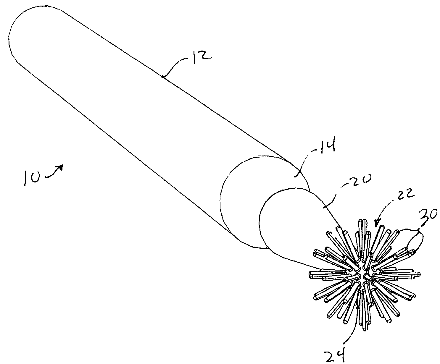
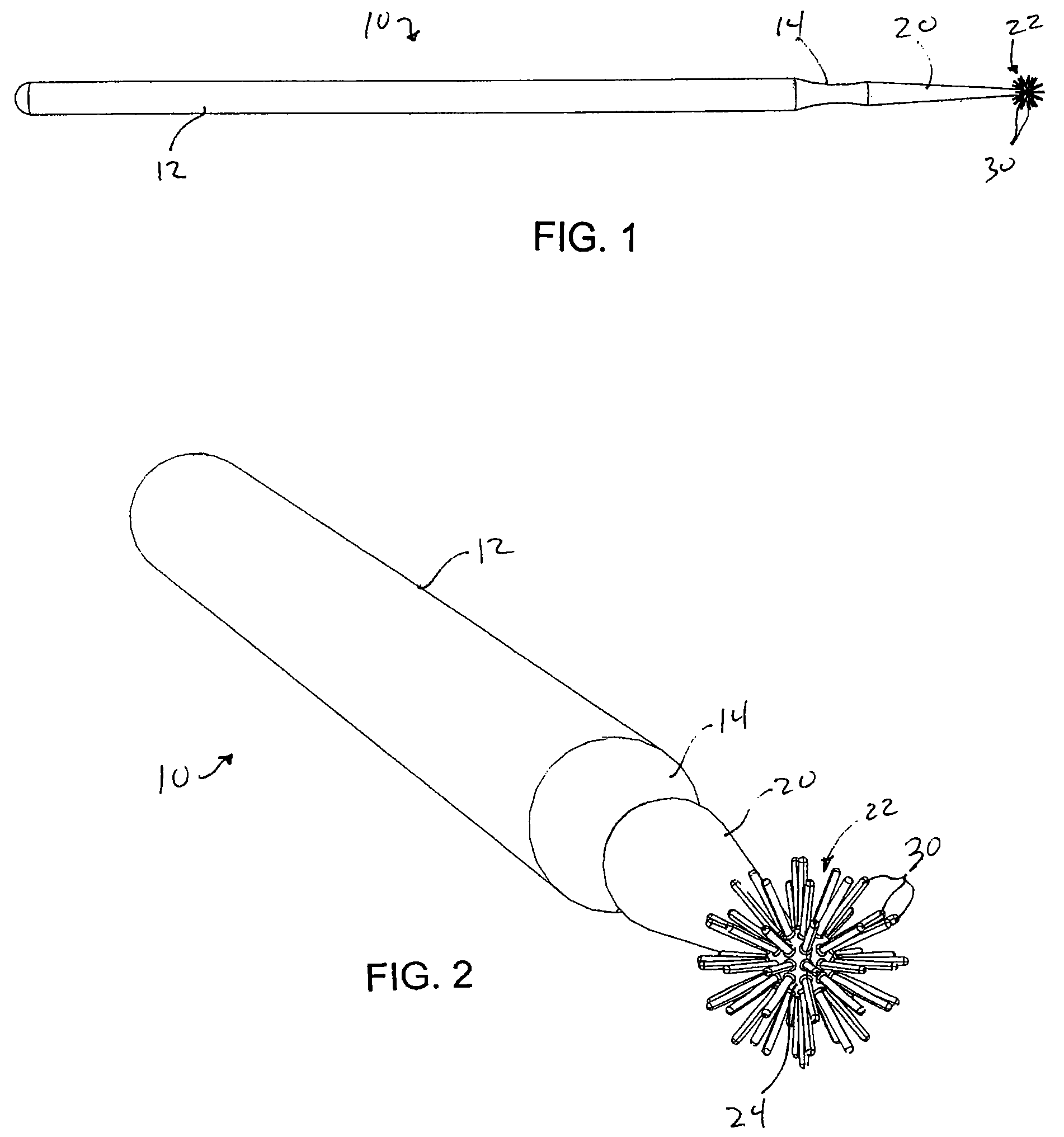
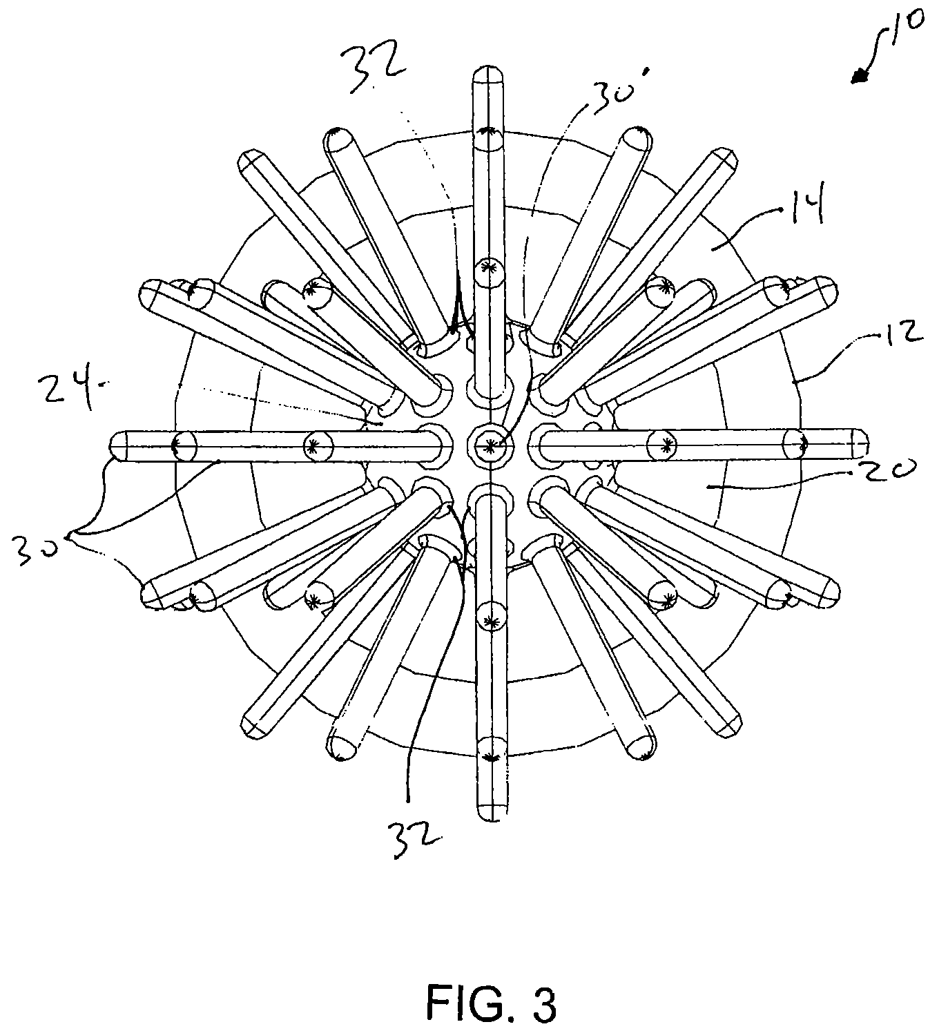
[0012]Referring to FIGS. 1-3 the present invention provides a dental device 10 that includes elongated handle 12 and a tip portion 20. The tip portion 20 is formed at a distal end of the handle 12 and has a tapered shape tapering to a smaller diameter tip end opposite the handle 12. The dental device 10 also includes an optional reduced diameter shoulder 14 formed between the elongated handle 12 and the tip portion 20. The shoulder 14 can facilitate gripping or holding of the handle 12 during use of the device 10. In one embodiment of this invention, the reduced diameter shoulder 14 can be formed to provide a weakened portion to permit a user to snap off the tip portion 20, from the handle 12. Such a separation permits a practitioner to choose a longer tool having an easier grip or a shorter tool having more maneuverability.

[0013]Various sizes, shapes, and configurations are available for the handle, tip portion, and shoulder. For example, the handle and / or tip portion can be square...


PUM


Abstract

A dental device including an elongated handle and a tip portion formed at a distal end of the handle and tapering to a tip end. A plurality of bristles is integrally molded with the tip end from a flexible polymer material.

Description

BACKGROUND OF THE INVENTION[0001]This invention relates generally to a dental device and, more particularly, to an anatomically sensitive endodontic applicator.[0002]Applicators are widely used in the dental profession to apply dental compositions or other materials to a tooth surface or a tooth preparation. Applicators are also used to clean the excess materials surrounding a tooth preparation or inside a tooth preparation. Applicators may also be used to dry a tooth preparation. Such applicators are typically disposable. Many currently available applicators include fibrous strands at a tip of the applicator. The possibility of the fibers becoming separated from the applicator tip or becoming loose inside a tooth preparation is real. Fiber coating the fibers to the tip of an applicator is no guarantee that all fibers will remain on the tip of the applicator as materials are applied to a tooth preparation. In other words, as the applicator is dipped into the tooth preparation, or ap...

Claims


Application Information

Patent Timeline
Patent Type & Authority Patents(United States)
IPC IPC(8): A46B1/00A46B9/04
CPCA46B9/04A46B1/00A61C3/005
Inventor MAISSAMI, FARI
Owner DENBUR
Learn More