Air valve for inflatable device

a technology for inflatable devices and air valves, which is applied in the field of valves, can solve the problems of not meeting the design specifications of inflatable devices, designed to be inflated at a high pressure, and taking a relatively long time to inflate and deflate inner tubes,

Active Publication Date: 2013-11-19
IDEAL TIME CONSULTANTS
View PDF29 Cites 20 Cited by
  • Summary
  • Abstract
  • Description
  • Claims
  • Application Information

AI Technical Summary

Problems solved by technology

However, they have several drawbacks, which in part result from being used outside of their design specifications.
One major drawback is that they are designed to be inflated at a high pressure.
This also means that it takes a relatively long time to inflate and deflate inner tubes.
There is also a risk of violent rupture because of the high potential energy of a high pressure reservoir.
Such an event could cause human injury or property damage.
Despite being inflated to a low pressure, these devices often have a substantial volume of inflatable space.
This makes fast and easy inflation and deflation an engineering challenge.
Furthermore, they must accommodate inflation from sources not capable of producing high inflation pressures.

Method used


Image

  • Air valve for inflatable device
  • Air valve for inflatable device
  • Air valve for inflatable device

Examples


second embodiment

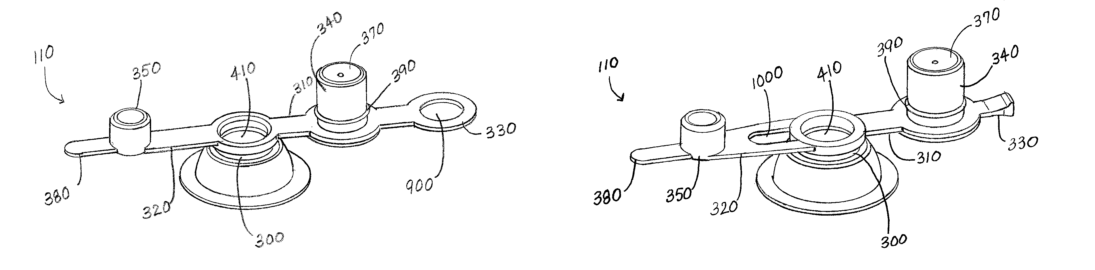
[0030]FIG. 9a is a perspective view of the air valve in a fully opened position. FIG. 9b is a perspective view of the embodiment shown in FIG. 9a in a partially opened position. FIG. 9c is a perspective view of the embodiment shown in FIG. 9a in a closed position. First tether 310 and second tether 320 may be coupled to opposite sides of housing 300. When air valve 110 is in a closed position, first pull tab 330 is adapted to fit between, on one side, check valve 340 and, on the other side, second tether 320 and second pull tab 380. First pull tab 330 is sufficiently thin to fit in between these parts in a closed position. First pull tab 330 is also shaped so as to fit into air valve 110 in a streamlined manner when air valve 110 is in a closed position. In this embodiment, first pull tab 330 is a flattened ring and surrounds cap 350 in a closed position of air valve 110. First pull tab 330 can be any shape that is ergonomic to pull and can fit between cap 350 and check valve 340 in...

third embodiment

[0032]FIG. 10a is a perspective view of the air valve in a fully opened position. FIG. 10b is a perspective view of the embodiment shown in FIG. 10a in a partially opened position. FIG. 10c is a perspective view of the embodiment shown in FIG. 10a in a closed position. In this embodiment, first tether 310 and second tether 320 are coupled to opposite sides of housing 300. In this embodiment, second tether 320 comprises orifice 1000 adjacent to housing 300. Orifice 1000 provides clearance for first pull tab 330, so that in a closed position of air valve 110, first pull tab 330 protrudes from orifice 1000. First pull tab 330 can be any shape that is ergonomic to pull and does not interfere with second tether 320 in a closed position.


PUM


Abstract

A housing has an upper end, a lower end, and an opening extending between the upper and lower ends, the housing being sealingly attachable to an inflatable device. A check valve has a body member with an upper end, a lower end, an outer surface sized and shaped to be selectively matingly received in the opening of the housing, and an inner surface defining a passageway. The check valve is coupled to the housing by a first tether. A cap has an upper end, a lower end, and an outer surface sized and shaped to be selectively matingly received in the passageway of the check valve. The cap is coupled to the housing by a second tether.

Description

FIELD OF THE INVENTION[0001]The apparatus described herein is generally directed to the field of valves; and, more directly, to the field of air valves for inflatable devices.BACKGROUND OF THE INVENTION[0002]The use of inflatable devices has long been associated with water sports and recreational activities involving water. For the most part, this has been the case because inflatable devices are generally capable of floating on water. With the explosion of the availability of inexpensive plastic products, recreational devices such as beach balls and water wings became increasingly common at pools and beaches during the latter half of the 20th century.[0003]Inflatable devices have also been used for more sophisticated recreational purposes. For example, inner tubes have traditionally been used as a simple watercraft. Inner tubes float in water, even with a rider in place, and provide a relatively ergonomic shape to secure the rider comfortably. They are also sufficiently durable for ...

Claims


Application Information

Patent Timeline
Patent Type & Authority Patents(United States)
IPC IPC(8): F16K15/20
CPCF16K15/202Y10T137/3724Y10T137/374
Inventor LAU, VINCENT W. S.
Owner IDEAL TIME CONSULTANTS
Why Eureka
Try Eureka