
Vacuum enhancing check valve

a check valve and vacuum-enhancing technology, applied in the direction of braking systems, process and machine control, instruments, etc., can solve the problems of loss of vacuum at the brake booster, vehicle braking, and insufficient pressure differential at all times, so as to reduce the cost and complexity of the vehicle and improve the reliability of the vehicl

Inactive Publication Date: 2006-01-26
FORD GLOBAL TECH LLC
View PDF14 Cites 100 Cited by
  • Summary
  • Abstract
  • Description
  • Claims
  • Application Information

AI Technical Summary

Benefits of technology

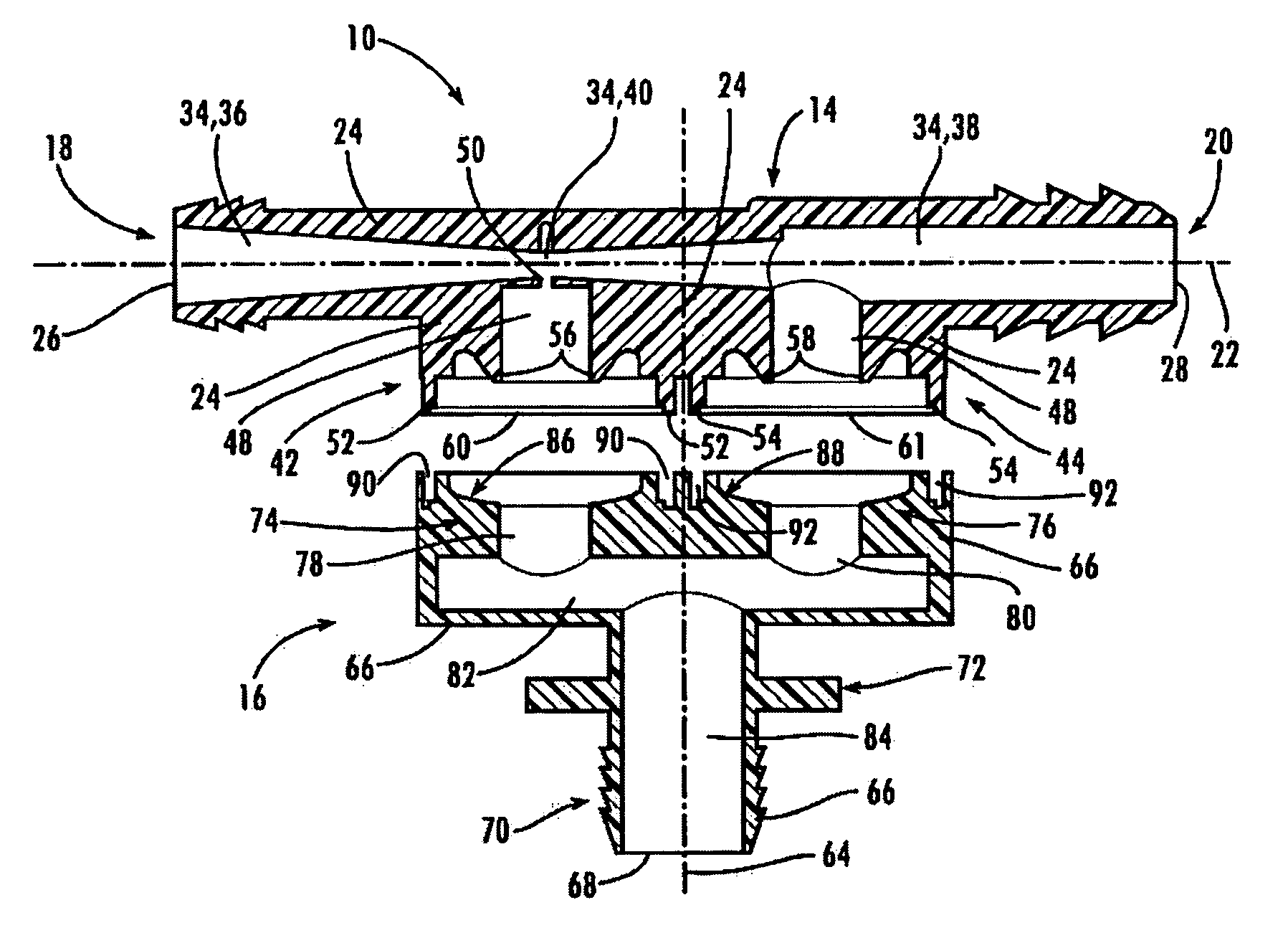
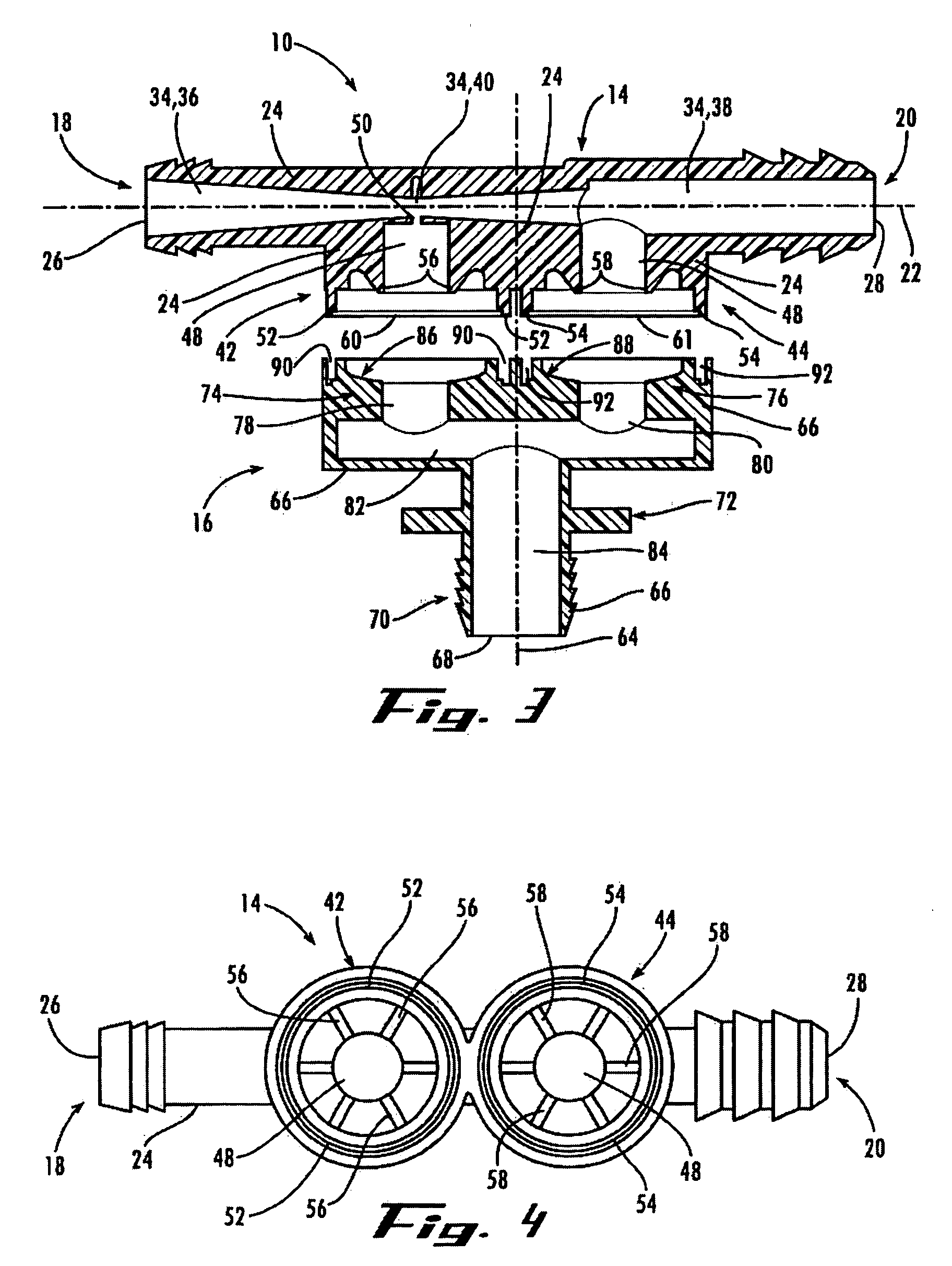
[0008] Advantageously, the vacuum enhancing check valve of the present invention attaches directly to the brake booster of a vehicle braking system and enables the flow of air from the front chamber of the brake booster, but not into the front chamber. Thus, the vacuum enhancing check valve eliminates the need for a check valve located within the brake booster to perform the same function. The vacuum enhancing check valve of the present invention also operates as an aspirator to increase the partial vacuum produced by the intake manifold of a vehicle's internal combustion engine for use by the vehicle's braking system and, potentially, by other vehicle devices or systems which require a vacuum assist. Formerly, such vacuum enhancement was performed by an aspirator positioned within a conduit between the intake manifold and braking system of a vehicle. Therefore, the vacuum enhancing check valve also eliminates the need for an aspirator located within a conduit and the need for a conduit extending between the aspirator and brake booster. Hence, the vacuum enhancing check valve replaces at least three or more components within a vehicle, thereby reducing the vehicle's cost and complexity and improving the vehicle's reliability. Further, the relative orientation of the air inlet ports and air outlet port of the vacuum enhancing check valve enables easy insertion of the second air inlet port directly into a brake booster absent interference with a conduit(s) attached before or after such insertion.

Problems solved by technology

The force causes the brake fluid to become pressurized and to then be supplied through a conduit to the brake actuators located at the vehicle's front and rear wheels, thus causing braking of the vehicle.
Unfortunately, the partial vacuum developed at the intake manifold may be lower under certain conditions and, hence, the pressure differential may not be sufficient at all times during operation of a vehicle for the vehicle to meet such standards.
For example, during cold start conditions or when a vehicle's transmission, power steering, or climate control compressor is engaged, a loss of vacuum at the brake booster may occur.

Method used


Image

  • Vacuum enhancing check valve
  • Vacuum enhancing check valve
  • Vacuum enhancing check valve

Examples


Embodiment Construction

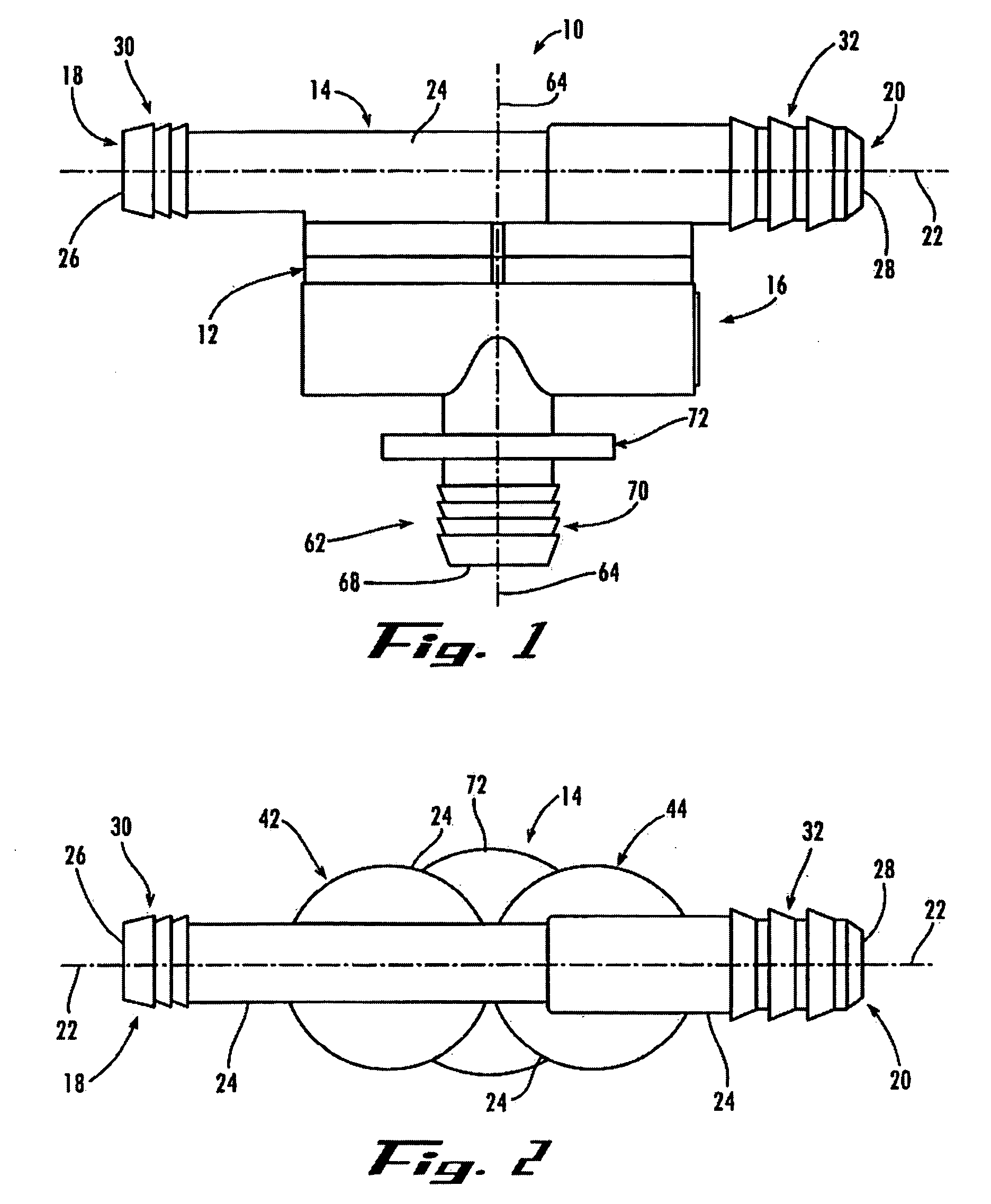
[0016] Referring now to the drawings in which like numerals represent like elements throughout the several views, FIG. 1 displays a side, elevational view of a vacuum enhancing check valve 10 in accordance with an exemplary embodiment of the present invention. The vacuum enhancing check valve 10 comprises a substantially one piece valve body 12 which is, generally, formed from a first valve portion 14 and a second valve portion 16 (see FIG. 3). The valve portions 14, 16 are, preferably, manufactured from an injection-molded, heat resistant, rigid plastic which can withstand the forces, pressures, and temperatures present during use attached to a braking system booster in a vehicle's engine compartment. The valve portions 14, 16 are securely joined together during manufacture by sonic welding, heating, or other appropriate method or technique. It should be understood that the valve portions 14, 16 may be manufactured from other suitable plastics, metals, or combinations thereof.

[001...


PUM


Abstract

A vacuum enhancing check valve for direct connection to a vehicle brake booster which increases the partial vacuum provided thereto and restricts possible air back flow into the brake booster. The valve comprises a venturi for reducing the pressure of air induced to flow between a first air inlet and an air outlet by a partial vacuum at a vehicle engine's intake manifold. By significantly reducing the air pressure, the valve enhances the partial vacuum available for provision to the brake booster. The venturi is also in air communication with a second air inlet directly attachable to the brake booster such that the air pressure at the second air inlet tends toward the enhanced partial vacuum within the venturi. A valve seat and seal member within the valve are cooperative to allow air flow from the second air inlet toward the venturi, but not in the reverse direction.

Description

FIELDS OF THE INVENTION [0001] The present invention relates, generally, to the fields of check valves and vehicle braking systems and, more specifically, to aspirating check valves for use with vehicle braking system boosters. BACKGROUND OF THE INVENTION [0002] Most of today's vehicle power braking systems utilize vacuum developed at the intake manifold of a vehicle's internal combustion engine to assist in their operation. Such vehicle power braking systems, generally, include a brake booster having a housing that encloses a front chamber and a rear chamber which is separated from the front chamber by a moveable wall. The vacuum developed at the intake manifold is communicated to the front chamber by a conduit to create a partial vacuum in the front and rear chambers which suspends the moveable wall. Thereafter, when a driver of the vehicle presses on the vehicle's brake pedal to apply braking, the vacuum provided to the rear chamber is interrupted and the rear chamber is opened t...

Claims


Application Information

Patent Timeline
IPC IPC(8): G05D7/00B60T13/52
CPCB60T13/52Y10T137/2567B60T17/04
Inventor ZAPARACKAS, ALGIS
Owner FORD GLOBAL TECH LLC
Learn More