
Manifold assembly

Inactive Publication Date: 2005-06-30
STRYKER CORP
View PDF23 Cites 99 Cited by
  • Summary
  • Abstract
  • Description
  • Claims
  • Application Information

AI Technical Summary

Benefits of technology

[0008] By incorporating an outlet check-valve on the outlet port, when vacuum pressure is not applied to the outlet port, the outlet-check valve will remain drip-free. Therefore, when the manifold assembly is removed from the medical waste collection device, any fluid remaining in the manifold assembly will not drip. This results in a more sterile manifold assembly.

Problems solved by technology

However, when the manifold assembly is removed from the medical waste collection device, the residual fluid that may linger in the manifold assembly is not prevented from dripping from the outlet port.

Method used


Image

  • Manifold assembly
  • Manifold assembly
  • Manifold assembly

Examples


second embodiment

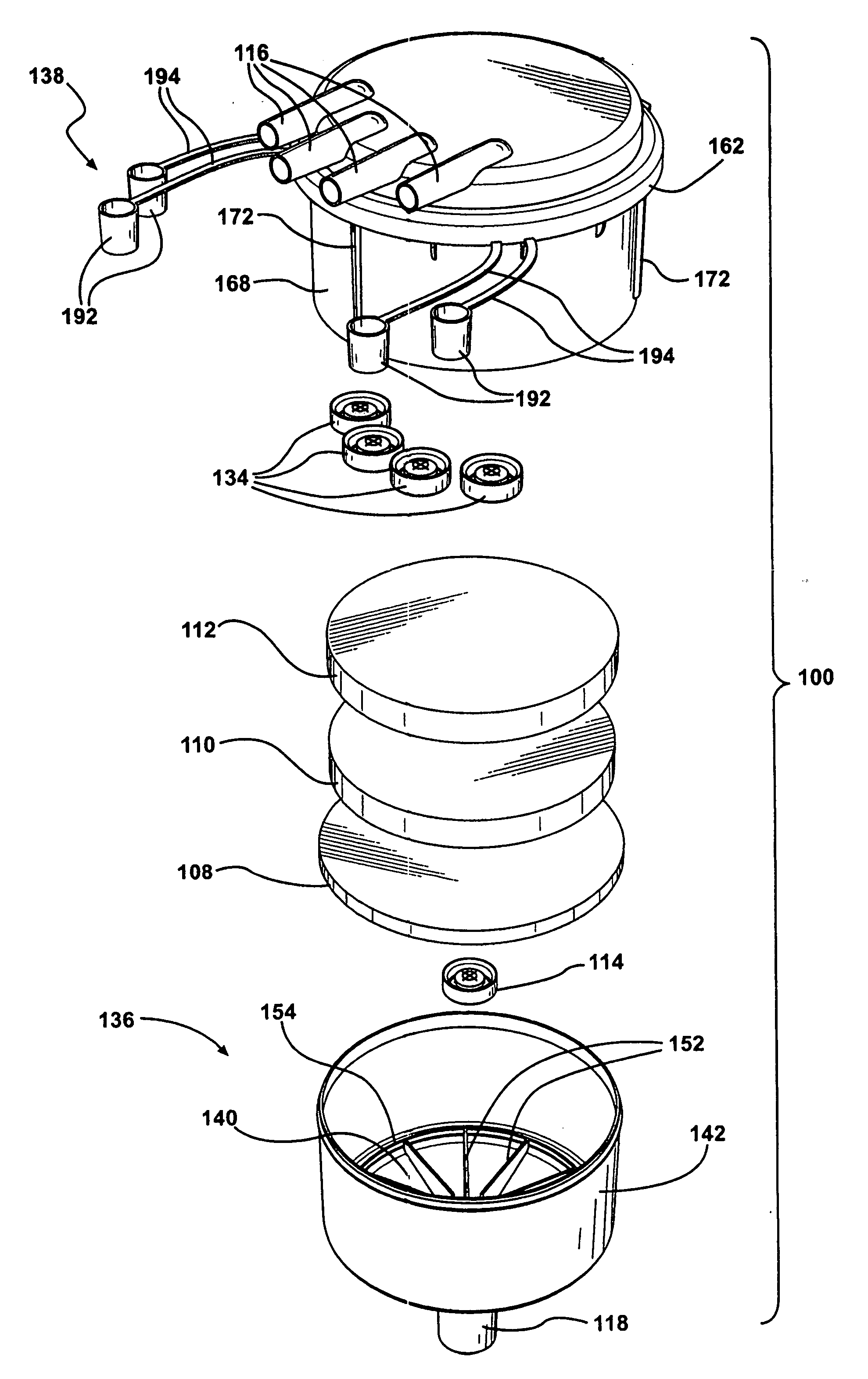
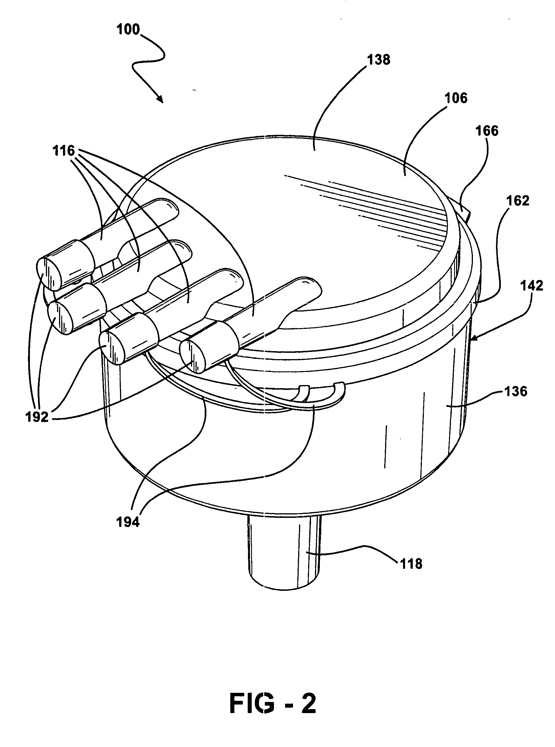
[0046] In the invention, shown in FIGS. 16-18, the inlet check-valves 134 are eliminated. This allows the inlet ports 116 to extend laterally and away from a face wall 196 of the manifold top 138. The port caps 192 are used to cover the inlet ports 116 when the manifold assembly 100 is removed from the medical waste collection device 104, thereby containing the system. The embodiment is acceptable if the inlet ports 116 are located above the residual fluid volume level and sufficiently separate from each other such that cross-contamination between the inlet ports 116 is not an issue.

third embodiment

[0047] In the invention, shown in FIGS. 19-21, the cover defines an access port 180 for collecting the material 102 from the filter 108, 110, 112 in the manifold housing 106. An access cover 181 closes the access port 180 and is removable for opening the access port 180 for the removal of material 102 from the filter 108, 110, 112 in the manifold housing 106 without having to remove the entire manifold top 138.

fourth embodiment

[0048] In the invention, shown in FIGS. 22-24, the inlet ports 116 are disposed within the peripheral wall 142 of the manifold body 136 instead of being disposed within the manifold top 138. With this embodiment, the inlet check-valves 134 are not required. The port caps 192 may be used to cover the inlet ports 116 when the manifold assembly 100 is removed from the medical waste collection device 104. The port caps 192 are joined to either the manifold top 138 or the manifold body 136 via the connection straps 194. This embodiment is acceptable with the inlet check-valves 134 eliminated if the inlet ports 116 are located above the residual fluid volume level and sufficiently separate from each other such that cross-contamination is not an issue. By integrating the inlet ports 116 within the peripheral wall 142 of the manifold body 136, manufacturability is improved by reducing the number of parts in the manifold assembly 100.

[0049] Additionally, it is preferable that the manifold ho...


PUM

PropertyMeasurementUnit
semi-transparentaaaaaaaaaa
vacuum pressureaaaaaaaaaa
porosityaaaaaaaaaa

Abstract

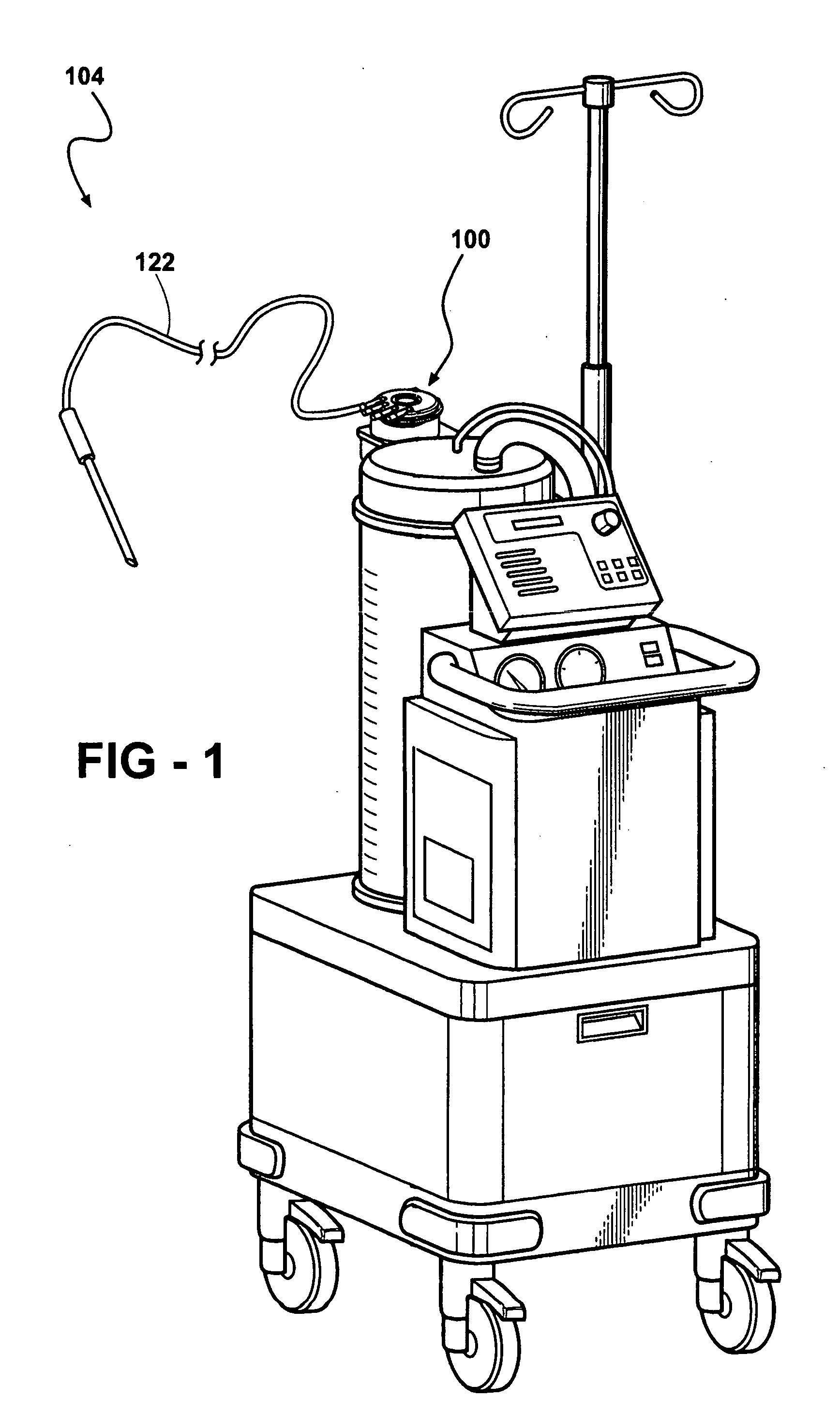
A manifold assembly (100) for directing and filtering material (102) from fluid flowing into a medical waste collection device (104) includes a plurality of inlet ports (116) and an outlet port (118) with a filter (108, 110, 112) disposed between the ports (116, 118) along a fluid path (120). An outlet check-valve (114) is disposed at the outlet port (118) for opening in response to a predetermined vacuum pressure applied to the outlet port (118) from the medical waste collection device (104).

Description

RELATED APPLICATION [0001] This application claims the benefit of U.S. Provisional Patent Application Ser. No. 60 / 512,671, which was filed on Oct. 20, 2003.BACKGROUND OF THE INVENTION [0002] 1. Field of the Invention [0003] This invention is directed to a filter system and, more particularly, to a filter system for removing solids or semi-solids from a fluid or liquid carrier. [0004] 2. Description of the Prior Art [0005] There are many uses for filter systems and / or devices for removing certain types of materials from a carrier, such as fluid. One such application is the removal of solid or semi-solid material, such as bone chips, flesh, blood clots or the like, from a fluid carrier generated during some types of medical procedures or surgeries by using a filtration process. This filtration process permits the fluid carrier to be treated separately from the material that is trapped by the filtration process. [0006] One such example of this type of filtration process is disclosed in...

Claims


Application Information

Patent Timeline
Patent Type & Authority Applications(United States)
IPC IPC(8): A61M1/00B01D35/153
CPCA61M1/0001B01D35/153A61M1/0056Y10T137/87571Y10T137/87676A61M1/79A61M1/60
Inventor HERSHBERGER, DAVIDISHAM, STEPHEN P.MACDONALD, BRUCESTALEY, KAREN L.ADLOFF, BRIAN
Owner STRYKER CORP
Learn More