Carbon dioxide production method

a carbon dioxide and production method technology, applied in the direction of hydrogen separation, hydrogen separation using solid contact, liquefaction, etc., can solve the problems of high cost of restarting, inability to readily obtain steam methane reforming plants, additional energy and capital costs, etc., and achieve the effect of advantageous improvement of hydrogen recovery

Active Publication Date: 2007-10-04
PRAXAIR TECH INC
View PDF11 Cites 105 Cited by
  • Summary
  • Abstract
  • Description
  • Claims
  • Application Information

AI Technical Summary

Benefits of technology

[0014] As is evident from the description given above, the carbon dioxide is taken from the synthesis gas stream rather than the tail gas stream. Moreover, since carbon dioxide is removed prior to the hydrogen pressure swing adsorption process, the recovery of hydrogen will advantageously be improved.

Problems solved by technology

It is to be noted, however, that when carbon dioxide is used for such purposes it has to be very pure and consequently, is not readily obtained from steam methane reforming plants.
A problem in practically utilizing either of the processes set forth in the patents listed above arises from the common use of the tail gas stream as part of the fuel to the steam methane reformer.
Any interruption in the fuel will cause the steam methane reformer system to go off-line resulting in a costly restart in which the primary fuel to the steam methane reformer, typically natural gas, must be utilized to bring the reformer back up to its operational temperature.
Another problem in utilizing tail gas is that it must be compressed before a crude carbon dioxide stream can be separated in a vacuum pressure swing adsorption process.
The compression step results in additional energy and capital costs.

Method used


Image

  • Carbon dioxide production method
  • Carbon dioxide production method
  • Carbon dioxide production method

Examples


example 1

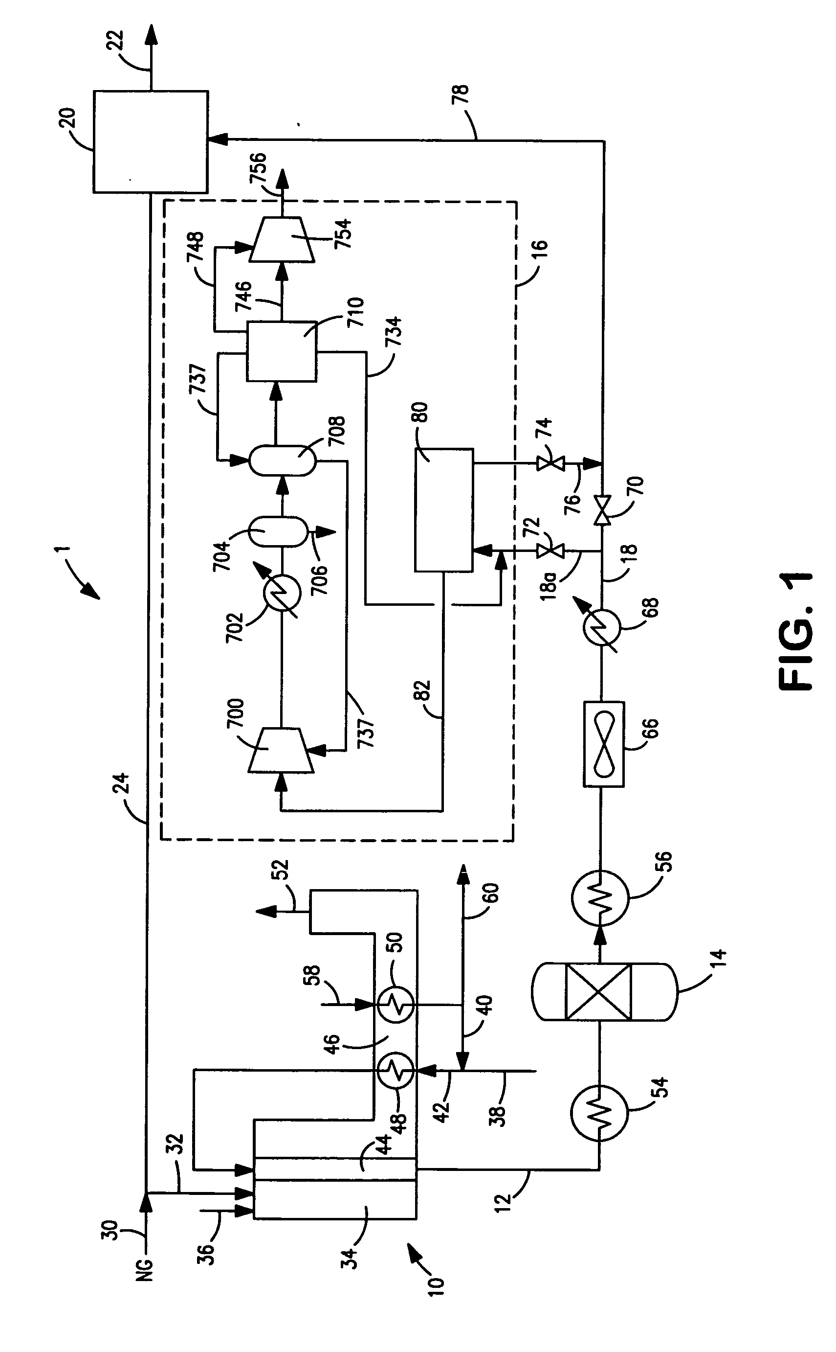
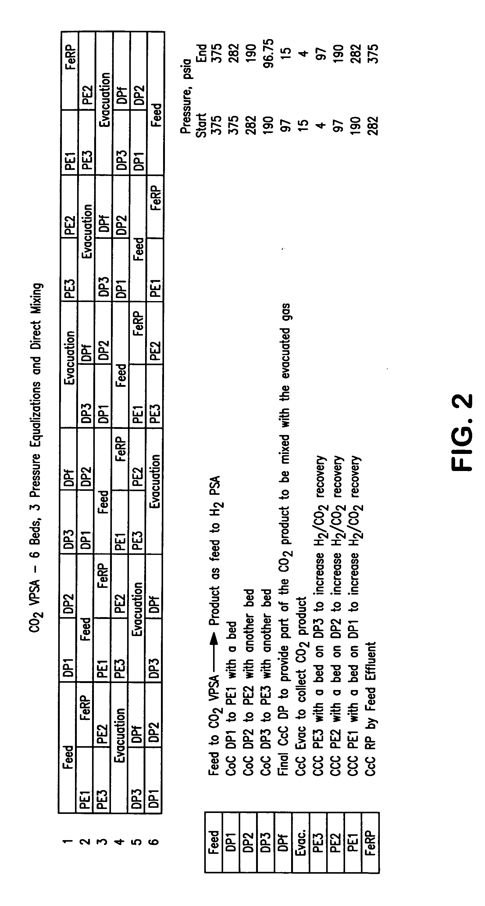
[0069] The following calculated example describes the details of various streams. The embodiment shown in FIG. 2 was used to report the results shown in Table 1. The values are based on the experimental data for the carbon dioxide vacuum pressure swing adsorption unit 80 and hydrogen pressure swing adsorption unit 20.

[0070] The overall carbon dioxide recovery in the above example was about 85 percent based on the amount of carbon dioxide in the synthesis gas stream 18. If the carbon dioxide-depleted vapor stream 734 is recycled and mixed with the synthesis gas stream 18 according to embodiment shown in FIG. 1, then the overall carbon dioxide recovery could be improved to about 95 percent.

TABLE 1Stream82afterdryerunit188270873473776Flow, MMscfd7514.215.63.91.664.7Pressure,38018700447135375psiaTemperature10010095555597° F.Composition(molfraction)H20.75700.11990.10980.43840.00520.8777CO20.16050.79250.82020.29380.96400.0297CO0.02490.01840.01720.06730.00410.0289CH40.05390.05460.05250....


PUM

PropertyMeasurementUnit
temperatureaaaaaaaaaa

Abstract

A method of producing a carbon dioxide product stream from a synthesis gas stream formed within a hydrogen plant having a synthesis gas reactor, a water-gas shift reactor, located downstream of the synthesis gas reactor to form the synthesis gas stream and a hydrogen pressure swing adsorption unit to produce a hydrogen product recovered from the synthesis gas stream. In accordance with the method the carbon dioxide from the synthesis gas stream by separating the carbon dioxide from the synthesis gas stream in a vacuum pressure swing adsorption system, thereby to produce a hydrogen-rich synthesis gas stream and a crude carbon dioxide stream and then purifying the crude carbon dioxide stream by a sub-ambient temperature distillation process thereby to produce the carbon dioxide product. A hydrogen synthesis gas feed stream to the hydrogen pressure swing adsorption unit is formed at least in part from the hydrogen rich stream.

Description

FIELD OF THE INVENTION [0001] The present invention relates to a method of producing a carbon dioxide product stream from a synthesis gas stream formed within a hydrogen plant having a synthesis gas reactor, a water-gas shift reactor to form the synthesis gas stream and a hydrogen pressure swing adsorption unit to form a hydrogen product. More particularly, the present invention relates to such a method in which the carbon dioxide is recovered from the synthesis gas stream by successively separating the carbon dioxide from the synthesis gas stream by a vacuum pressure swing adsorption process and a sub-ambient temperature distillation process. Even more particularly, the present invention relates to such a method having application to use of the carbon dioxide product stream for enhanced oil recovery or for sequestration. BACKGROUND OF THE INVENTION [0002] Synthesis gas contains carbon monoxide and hydrogen that can be further purified to produce hydrogen and carbon monoxide product...

Claims


Application Information

Patent Timeline
Patent Type & Authority Applications(United States)
IPC IPC(8): C07C27/06C01B32/50
CPCB01D53/0462Y02C10/12B01D53/0476B01D2253/10B01D2253/106B01D2256/16B01D2256/22B01D2257/504B01D2257/80B01D2259/40069B01D2259/40071B01D2259/40073B01D2259/4062C01B3/384C01B3/48C01B3/56C01B31/20C01B2203/0233C01B2203/0283C01B2203/043C01B2203/0475C01B2203/0816C01B2203/1241C01B2203/1288C01B2203/148C01B2203/86F25J3/0223F25J3/0252F25J3/0266F25J2200/02F25J2200/70F25J2205/02F25J2205/40F25J2205/60F25J2205/66F25J2205/82F25J2210/04F25J2220/82F25J2230/30F25J2230/80F25J2240/40F25J2245/02F25J2260/80F25J2270/02Y02C10/08B01D53/047C01B32/50F25J3/08F25J2215/80Y02P20/151Y02P30/00Y02C20/40F25J3/02
Inventor SHAH, MINISH MAHENDRAKUMAR, RAVIHOWARD, HENRY EDWARDNEU, BERNARD THOMASBONAQUIST, DANTE PATRICKBILLINGHAM, JOHN FREDRIC
Owner PRAXAIR TECH INC
Why Eureka
Try Eureka