Hydrogen purification optimization system

a hydrogen purification and optimization system technology, applied in the direction of hydrogen separation using solid contact, combustible gas production, separation processes, etc., can solve the problems of reducing the efficiency of hydrogen recovery using psa units, reducing the efficiency of hydrogen recovery, and reducing the load on steam reformers. , to achieve the effect of maximizing hydrogen recovery, increasing total hydrogen recovery, and reducing the load on steam reformers

Active Publication Date: 2007-01-25
SAUDI ARABIAN OIL CO
View PDF12 Cites 7 Cited by
  • Summary
  • Abstract
  • Description
  • Claims
  • Application Information

AI Technical Summary

Benefits of technology

[0010] The method of hydrogen recovery of the present invention, when compared with previously proposed methods, has the advantages of: increasing total hydrogen recovery by maximizing hydrogen recovery from refinery offgases, reducing the load on the steam reformer by lowering the reformer feed stream, reducing refinery fuel gas consumption in the steam reformer furnace, reducing the amount of refinery offgases burned as fuel or sent to flare, reducing the load on the PSA unit receiving feed from refinery offgases, and enriching the hydrocarbon content and heating value of the tail gas from the PSA unit fed by the steam reformer product stream.

Problems solved by technology

However, these and other previously proposed arrangements for hydrogen recovery using PSA units suffer from a number of disadvantages.
For example, in the case where multiple PSA units are being utilized to treat different feed streams, if some portion of the feed stream for one of the PSA units was to exceed the capacity of the PSA unit, the excess portion is not effectively utilized to promote hydrogen recovery.
Another disadvantage of previously proposed arrangements using multiple PSA units is that in order to achieve maximum hydrogen recovery, each PSA unit must be operated at or near maximum capacity.
Operating these units at such high capacity damages the adsorbent material within the units by increasing the likelihood that impurities will be carried over between adsorbent layers.
Also, operating some of these PSA units at or near maximum capacity requires an increased feed stream and fuel gas stream for the unit operation providing the feed stream, which raises operating costs.

Method used


Image

  • Hydrogen purification optimization system
  • Hydrogen purification optimization system

Examples


example

[0018] An embodiment of the present invention was implemented in a refinery setting and evaluated to determine the effect on various process data. A summary of the process data before and after implementation of the present invention is shown in Table 1.

TABLE 1PROCESS DATA COMPARISONBeforeAfterimplemen-implemen-Process ParametertationtationUnitsButane feed to steam reformer22,00013,300MLB / HRFlow diverted to second PSA unit0.00.63MMSCFDfrom refinery offgas streamFuel gas flow to reformer furnace5.53.0MLB / HRRefinery gases flared and / or0.630.0MSCFHburnedSteam reformer outlet stream74.075.0mol % H27.07.0mol % CO16.016.0mol % CO21.00.9mol % C1

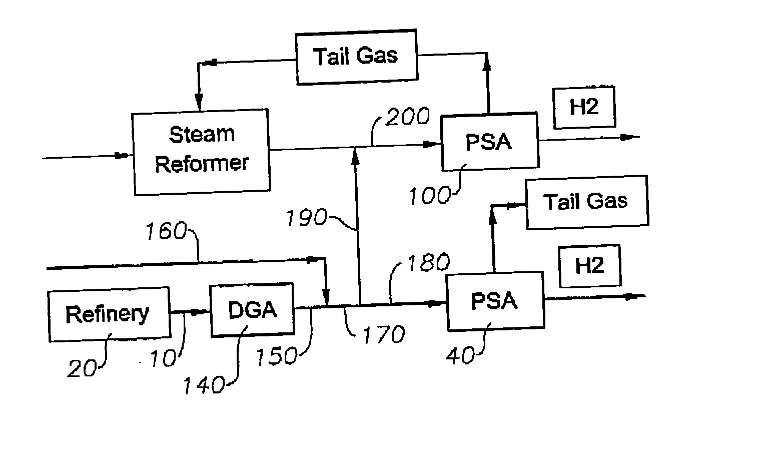
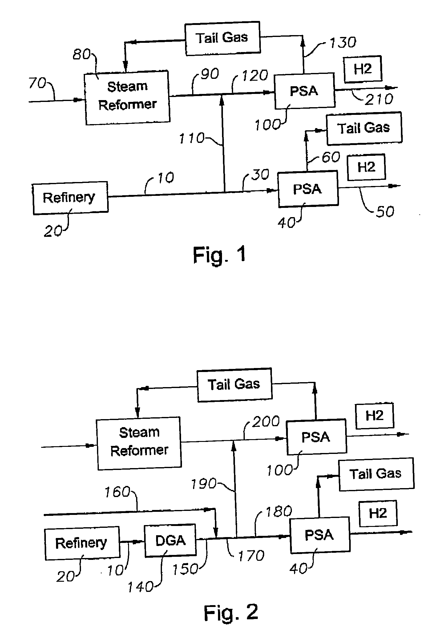
[0019] After implementation of the present invention as illustrated in Table 1, the butane feed to the steam reformer was reduced by about 1000 BBL / day, and the steam reformer furnace fuel gas consumption was reduced by about 1.5 MMSCFH. Also, the flared gases were reduced by about 630 MSCFH, and instead utilized for hydrogen production. At about ...


PUM

PropertyMeasurementUnit
pressureaaaaaaaaaa
pressureaaaaaaaaaa
operating pressureaaaaaaaaaa

Abstract

A method of hydrogen recovery in refineries and petrochemical operations in which some or all of the feed streams for separate PSA units are combined and utilized as feed for a single PSA unit, and in which some or all of steam reformer product and refinery offgas streams being used as feed streams for separate PSA units are combined and utilized as feed for a single PSA unit. Total hydrogen recovery is increased by maximizing hydrogen recovery from refinery offgases. The load on the steam reformer is reduced by lowering the reformer feed stream. Refinery fuel gas consumption is reduced in the steam reformer furnace. The amount of a PSA feed stream being burned as fuel or sent to flare is reduced. The load on the PSA unit receiving feed from refinery offgases is reduced. The hydrocarbon content and heating value of the tail gas from the PSA unit fed by the steam reformer product stream is enriched.

Description

BACKGROUND OF THE INVENTION [0001] 1. Field of the Invention [0002] The present invention relates to the recovery of hydrogen from gas mixtures and, more particularly, to a method for obtaining increased hydrogen recovery from oil refineries and petrochemical or natural gas operations by combining a steam reformer hydrogen product stream with an offgas stream and utilizing the combined stream as feed for a single pressure swing adsorption (PSA) unit. [0003] 2. Description of the Related Art [0004] The use of pressure swing adsorption (PSA) to separate gas mixtures is well known in the art. More specifically, it is known that one or more PSA units can be used to recover hydrogen from streams containing mixtures of hydrogen and hydrocarbons in refineries and petrochemical operations. For example, it has been previously proposed that a single PSA unit be utilized within a refinery or petrochemical operation to recover hydrogen from a flow stream. U.S. Pat. No. 5,435,836 by Anand et al....

Claims


Application Information

Patent Timeline
Patent Type & Authority Applications(United States)
IPC IPC(8): C10J3/46B01D53/047C01B3/56
CPCB01D53/047B01D2256/16B01D2256/24B01D2257/702B01D2259/40001C01B2203/0485C01B2203/043C01B2203/047C01B2203/0475C01B2203/048C01B3/56
Inventor AL-BABTAIN, IBRAHIM M.
Owner SAUDI ARABIAN OIL CO
Why Eureka
Try Eureka