Hydrogen production process with carbon dioxide recovery

Inactive Publication Date: 2014-11-13
LINDE AG
View PDF5 Cites 15 Cited by
  • Summary
  • Abstract
  • Description
  • Claims
  • Application Information

AI Technical Summary

Benefits of technology

[0007]In one embodiment, there is disclosed an improved method for increasing hydrogen recovery of a hydrogen production plant, the improvement comprising recovering additional hydrogen from a low pressure waste gas stream from a pressure swing adsorption unit producing hydrogen, by feeding the lo

Problems solved by technology

Particularly in the case of small hydrogen production units, the tail or waste gas stream is oft

Method used


Image

  • Hydrogen production process with carbon dioxide recovery
  • Hydrogen production process with carbon dioxide recovery

Examples


Example

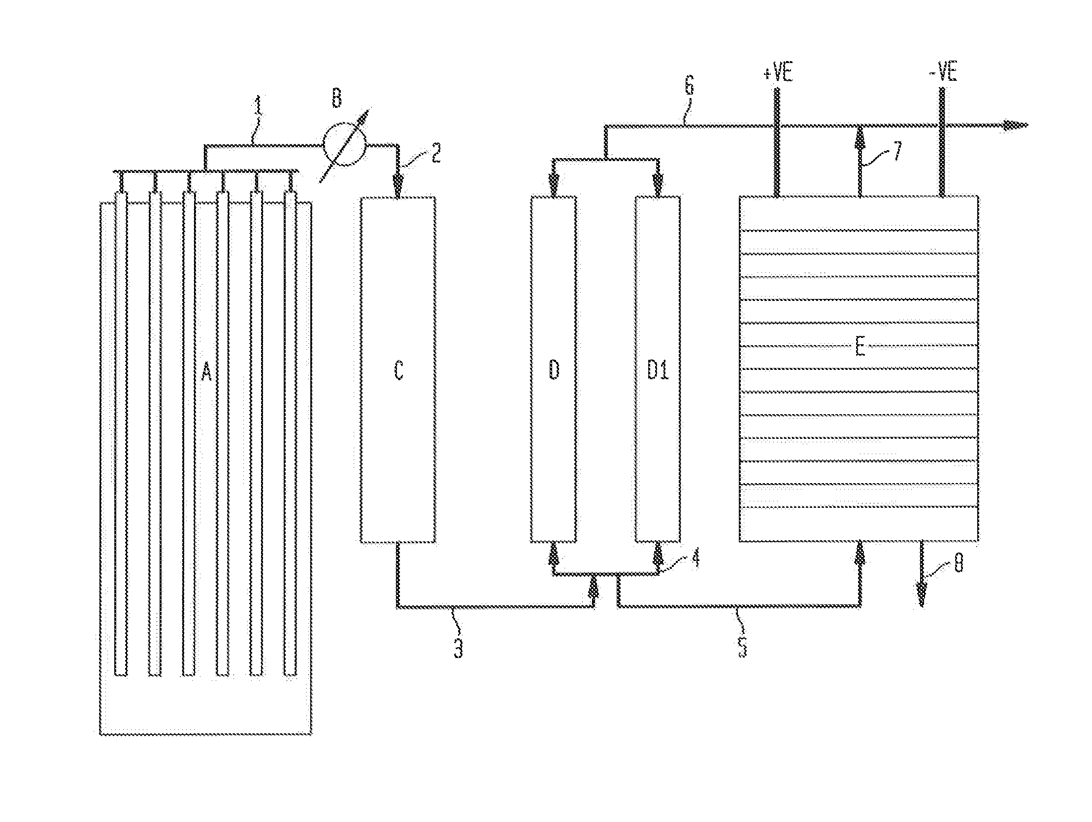
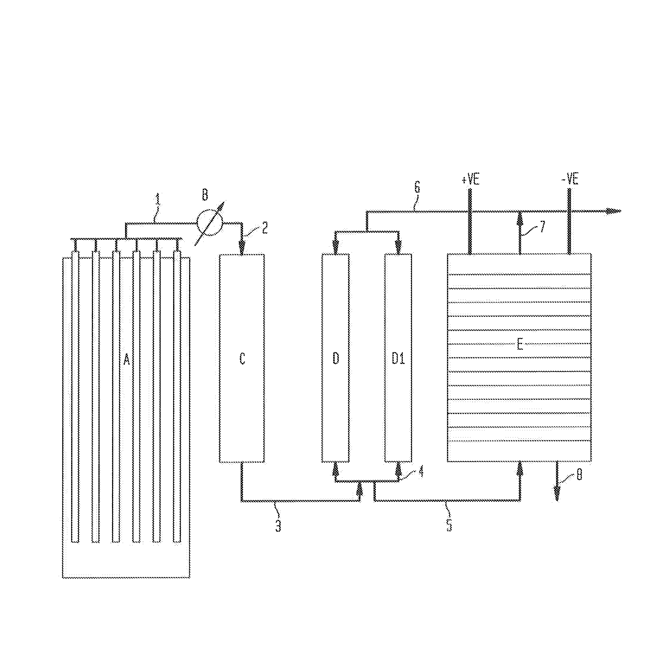
[0020]Turning to the FIGURE, there is shown a schematic representation of the process for separating hydrogen from the waste gas stream of a pressure swing adsorption system using an electrochemical cell.

[0021]A reformation unit A will produce a synthesis gas mixture. The reformation process will typically be a steam or a carbon dioxide (or a mixture of steam and CO2) reformation process whereby steam or carbon dioxide is fed along with a hydrocarbon such as methane. These reactants are reacted in the presence of a metal-based catalyst where they will form the synthesis gas mixture of hydrogen, carbon monoxide, carbon dioxide, unreacted methane and water, as well as trace constituents.

[0022]The synthesis gas mixture is fed through line 1 to a cooler B whereby the synthesis gas mixture is reduced in temperature from 700° to 900° C. to a temperature of ˜300° C. to near ambient. The cooled synthesis gas mixture is optionally fed through line 2 to a water gas shift reaction unit whereby...


PUM


Abstract

A method for producing hydrogen by performing the steps of feeding a synthesis gas mixture to a pressure swing adsorption unit; producing hydrogen from the synthesis gas mixture in the pressure swing adsorption unit; feeding the remainder of the synthesis gas mixture at low pressure to an electrochemical cell wherein hydrogen is separated from the remainder of the synthesis gas mixture and is simultaneously pressurized; feeding the pressurized hydrogen from the electrochemical cell to join with the hydrogen generated in the pressure swing adsorption unit and recovering the combined hydrogen product. The synthesis gas mixture may be from a reformation unit and it may be subject to a water gas shift reaction. In addition to the production of hydrogen, the separation of hydrogen in the electrochemical cell increases the concentration of carbon dioxide in the residual waste gas and enables carbon dioxide recovery.

Description

BACKGROUND OF THE INVENTION[0001]Conventional hydrogen production plants that are based on steam or carbon dioxide reforming of methane, or partial oxidation or auto-thermal reforming processes typically comprise a pressure swing adsorption (PSA) unit downstream to recover high purity hydrogen at high pressure. In the process, typically 70 to 90 percent hydrogen is recovered, depending on operating parameters such as the feed pressure and flow rate, feed H2 concentration and the desired product purity. As a result, a waste gas or tail gas is generated at a low, nearly atmospheric pressure, containing unrecovered hydrogen, as well as carbon dioxide, carbon monoxide, methane, water and other trace components. This stream is typically used as a fuel for the reformer furnace.[0002]However, if the hydrogen present in the waste gas stream can be recovered at high purity, it has greater value as a chemical compared to its fuel value. This is of particular note in auto-thermal or partial ox...

Claims


Application Information

Patent Timeline
IPC IPC(8): C25B1/02C01B3/50
CPCC01B3/50C01B3/508C25B1/02C01B3/56C01B2203/146C01B2203/04C01B2203/043C01B2203/0205
Inventor TAMHANKAR, SATISH S.KRISHNAMURTHY, RAMACHANDRAN
Owner LINDE AG
Why Eureka
Try Eureka