Magnetic recording head slider comprising bond pad having a probe contact area and a solder contact area

a magnetic recording and slider technology, applied in the direction of recording information storage, maintaining head carrier alignment, instruments, etc., can solve the problems of affecting the reliability of bond pads, affecting the ability to test bond pads, and affecting the spacing between components

Active Publication Date: 2013-11-19
WESTERN DIGITAL TECH INC
View PDF24 Cites 51 Cited by
  • Summary
  • Abstract
  • Description
  • Claims
  • Application Information

AI Technical Summary

Problems solved by technology

The addition of components to assemblies may further encroach upon the spacing between one component and another.
Maintaining spacing between components may be significant where adjacent components may inadvertently form an electrical connection.
However, as bond pads may become smaller to accommodate additional bond pads in an area, ...

Method used


Image

  • Magnetic recording head slider comprising bond pad having a probe contact area and a solder contact area
  • Magnetic recording head slider comprising bond pad having a probe contact area and a solder contact area
  • Magnetic recording head slider comprising bond pad having a probe contact area and a solder contact area

Examples


Embodiment Construction

[0023]The detailed description set forth below is intended as a description of various configurations of the subject technology and is not intended to represent the only configurations in which the subject technology may be practiced. The appended drawings are incorporated herein and constitute a part of the detailed description. The detailed description includes specific details for the purpose of providing a thorough understanding of the subject technology. However, it will be apparent to those skilled in the art that the subject technology may be practiced without these specific details. In some instances, well-known structures and components are shown in block diagram form in order to avoid obscuring the concepts of the subject technology. Like components are labeled with identical element numbers for ease of understanding.

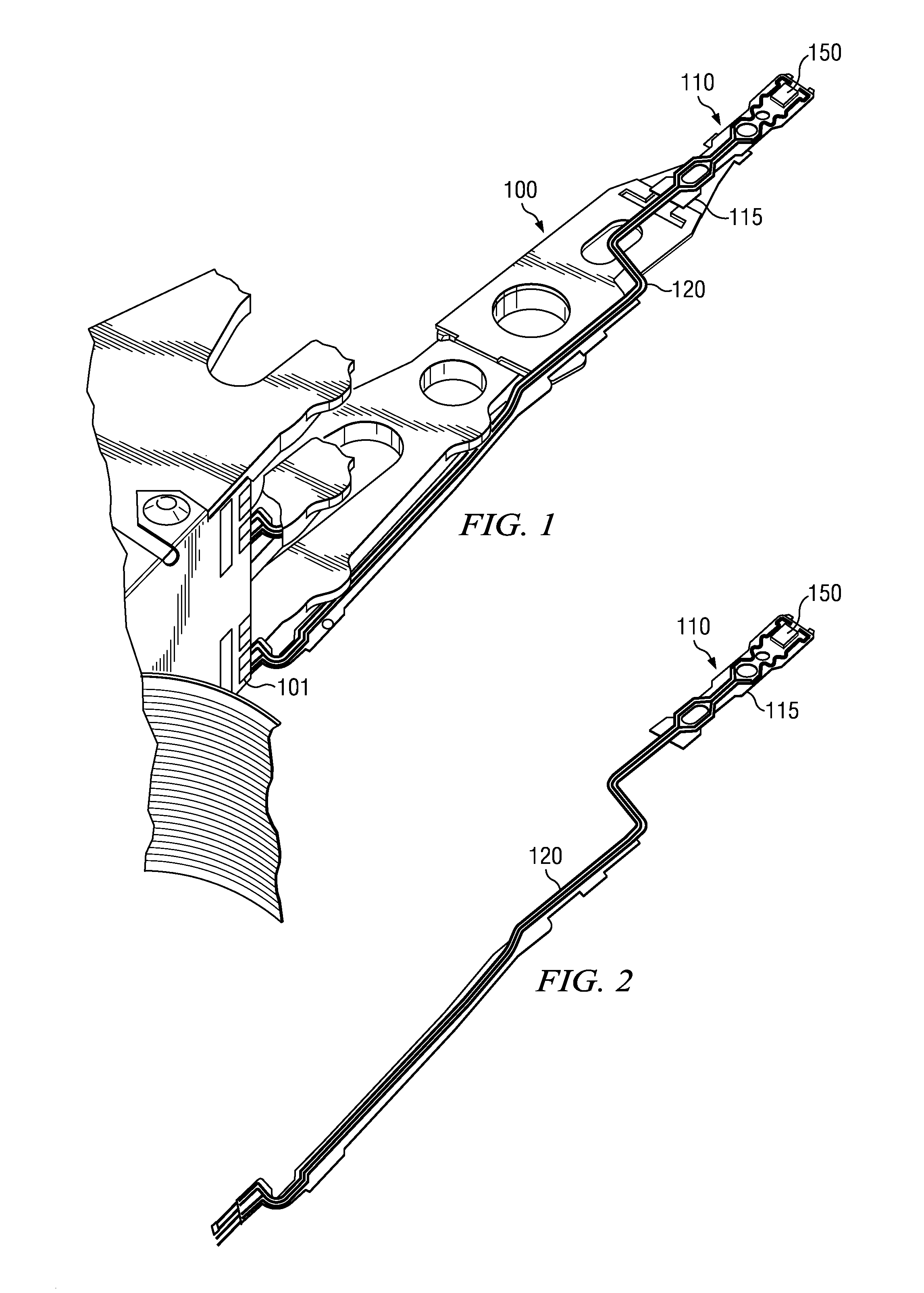
[0024]FIG. 1 shows a perspective view of a portion of an actuator arm 100. The actuator arm 100 includes a head gimbal assembly 110, a suspension arm 115, a m...


PUM


Abstract

Examples of a magnetic recording head slider, a head gimbal assembly and methods of manufacturing each are disclosed. The magnetic recording head slider may comprise a slider body and a plurality of bond pads formed on a trailing edge of the slider body. Each of the plurality of bond pads may include a probe contact area and a soldering contact area. The probe contact area may be larger than the soldering contact area. The head gimbal assembly may include a suspension arm with conductive leads. A plurality of bond pads may be formed on the suspension arm in contact with the ends of the conductive leads. A width of a proximal portion of each of the bond pads may be greater than a width of a distal portion of each of the plurality of bond pads. The methods may include forming the above-described structures.

Description

BACKGROUND[0001]The subject disclosure relates to disk drive components, and more particularly, to bond pad configurations for magnetic recording head sliders.[0002]The assembly and testing of hard disk drive components may include components positioned adjacent to one another in a relatively tight spacing. The addition of components to assemblies may further encroach upon the spacing between one component and another. Maintaining spacing between components may be significant where adjacent components may inadvertently form an electrical connection.[0003]For example, a hard disk drive magnetic recording head slider may include multiple bond pads that are eventually bonded to another set of pads on a suspension arm assembly. In a typical magnetic recording head slider, bond pads may be formed in a uniform rectangular shape. The bond pads may be arranged side by side spaced to one another and solder bonded to respective bond pads on the suspension arm assembly. Maintaining a minimum p...

Claims


Application Information

Patent Timeline
IPC IPC(8): G11B5/60
CPCG11B5/4826G11B5/4853G11B5/295G11B5/486
Inventor PUTTICHAEM, WACHIRATOKAEW, ADISAKPAN, TZONG-SHII
Owner WESTERN DIGITAL TECH INC
Why Eureka
Try Eureka