Boat propulsion system and method for controlling boat propulsion system

a boat propulsion and boat propulsion technology, applied in the direction of marine propulsion, vessel construction, instruments, etc., can solve the problems of limiting the steering angle of the propulsion unit, unable to adequately steer the outside propulsion unit, and unable to achieve the effect of sufficient propulsion for

Active Publication Date: 2013-11-19
YAMAHA MOTOR CO LTD
View PDF14 Cites 29 Cited by
  • Summary
  • Abstract
  • Description
  • Claims
  • Application Information

AI Technical Summary

Benefits of technology

[0012]In a preferred embodiment of the present invention, the plurality of boat propulsion units are controlled so that the point of action of the first resultant force is positioned behind the point of action of the second resultant force when an operational command from the operation device to travel in the lateral direction is received. The first resultant force is the resultant force of propulsion forces generated by the first port-side propulsion unit and the first starboard-side propulsion unit. In other words, the first resultant force is a resultant force of the propulsion forces generated by the inside two propulsion units. The second resultant force is a resultant force of propulsion forces generated by the second port-side propulsion unit and the second starboard-side propulsion unit. In other words, the second...

Problems solved by technology

However, the outside two propulsion units are auxiliary propulsion units and are not steered.
The following problems arise when the control in the two-engine boat of Japanese Laid-open Patent Application No. 2005-319967 is applied without modification to a four-engine boat when the boat is made to move laterally on the basis of an operational command provided by an operation device in a boat equipped with four propulsion units.
However,...

Method used


Image

  • Boat propulsion system and method for controlling boat propulsion system
  • Boat propulsion system and method for controlling boat propulsion system
  • Boat propulsion system and method for controlling boat propulsion system

Examples


Embodiment Construction

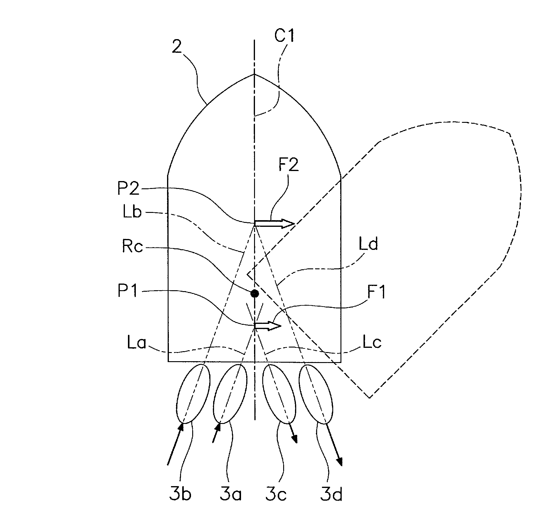
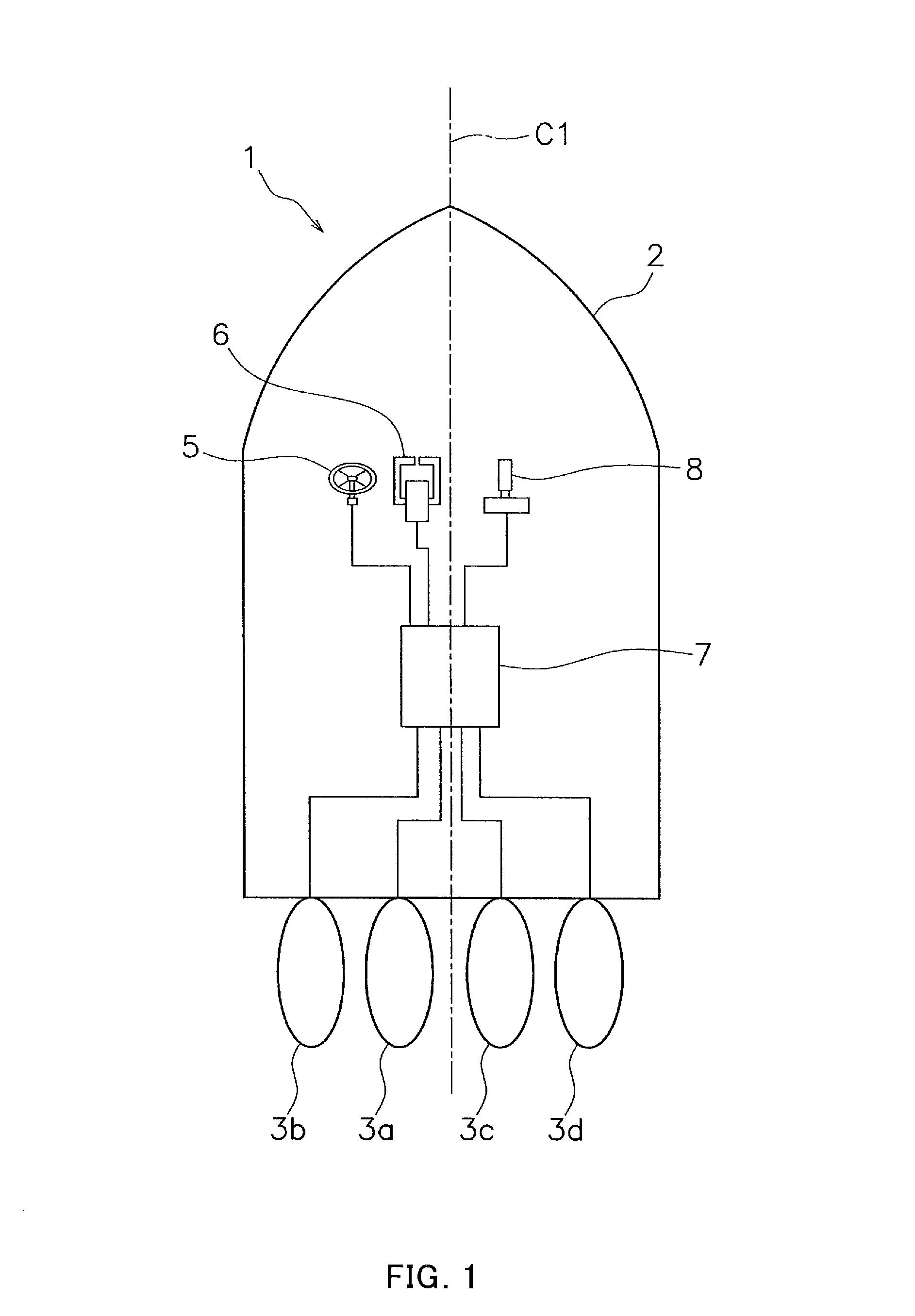
[0024]Preferred embodiments of the present invention are described below with reference to the drawings. FIG. 1 is a schematic view showing a boat 1. The boat 1 is equipped with a boat propulsion system according to a preferred embodiment of the present invention. The boat 1 includes a hull 2 and a plurality of boat propulsion units 3a to 3d, as shown in FIG. 1. The boat propulsion units 3a to 3d are preferably outboard engines. Specifically, the boat 1 is provided with a first port-side propulsion unit 3a (hereinafter referred to as “first port unit 3a”), a second port-side propulsion unit 3b (hereinafter referred to as “second port unit 3b”), a first starboard-side propulsion unit 3c (hereinafter referred to as “first starboard unit 3c”), and a second starboard-side propulsion unit 3d (hereinafter referred to as “second starboard unit 3d”).

[0025]The boat propulsion units 3a to 3d are mounted on the stern of the hull 2. The boat propulsion units 3a to 3d are disposed in a line in t...


PUM


Abstract

A control unit for a boat propulsion system individually controls the forward and reverse propulsion directions, the propulsion force, and the steering angle of each of a plurality of boat propulsion units so that a point of action of a first resultant force is positioned behind a point of action of a second resultant force when the control unit receives an operational command from an operation device for travel in a lateral direction of a hull. The first resultant force is a resultant force of propulsion forces generated by the first port-side propulsion unit and the first starboard-side propulsion unit. The second resultant force is a resultant force of propulsion forces generated by the second port-side propulsion unit and the second starboard-side propulsion unit.

Description

BACKGROUND OF THE INVENTION[0001]1. Field of the Invention[0002]The present invention relates to a boat propulsion system and a method for controlling a boat propulsion system.[0003]2. Description of the Related Art[0004]There are boats equipped with a plurality of boat propulsion units in order to improve high-speed performance, turning performance, steering stability, and other boat performance factors. An operation device capable of outputting operational commands at least in the directions of forward, reverse, left, and right is equipped in the boat in order to facilitate, even for a user without skill in operating a boat, operation of a boat provided with a plurality of boat propulsion units.[0005]For example, Japanese Laid-open Patent Application No. 2005-319967 discloses a boat in which two propulsion units are operated by a joystick. In this boat, two propulsion units are controlled so that the boat is moved laterally or rotated based on the operational command provided by j...

Claims


Application Information

Patent Timeline
IPC IPC(8): G05D1/00B63H25/00
CPCB63H25/42B63H20/12B63H2020/003
Inventor KANNO, ISAO
Owner YAMAHA MOTOR CO LTD
Why Eureka
Try Eureka