
Motor vehicle pedal having a safety device

a safety device and motor vehicle technology, applied in the field of pedals, to achieve the effect of increasing the robustness of the devi

Inactive Publication Date: 2013-11-26
AKWEL SA
View PDF13 Cites 2 Cited by
  • Summary
  • Abstract
  • Description
  • Claims
  • Application Information

AI Technical Summary

Benefits of technology

The solution ensures complete release of the pedal assembly from the bracket during an impact, reducing the risk of injury by allowing the pedal to pivot freely and fall, enhancing safety and reliability while maintaining simplicity and cost-effectiveness.

Problems solved by technology

The residual friction on these plates opposes the movement of the shaft, therefore of the pedal, resulting in the need to impose the travel path of this shaft through complete guiding in the slots and by the driving lever.

Method used


Image

  • Motor vehicle pedal having a safety device
  • Motor vehicle pedal having a safety device
  • Motor vehicle pedal having a safety device

Examples


Embodiment Construction

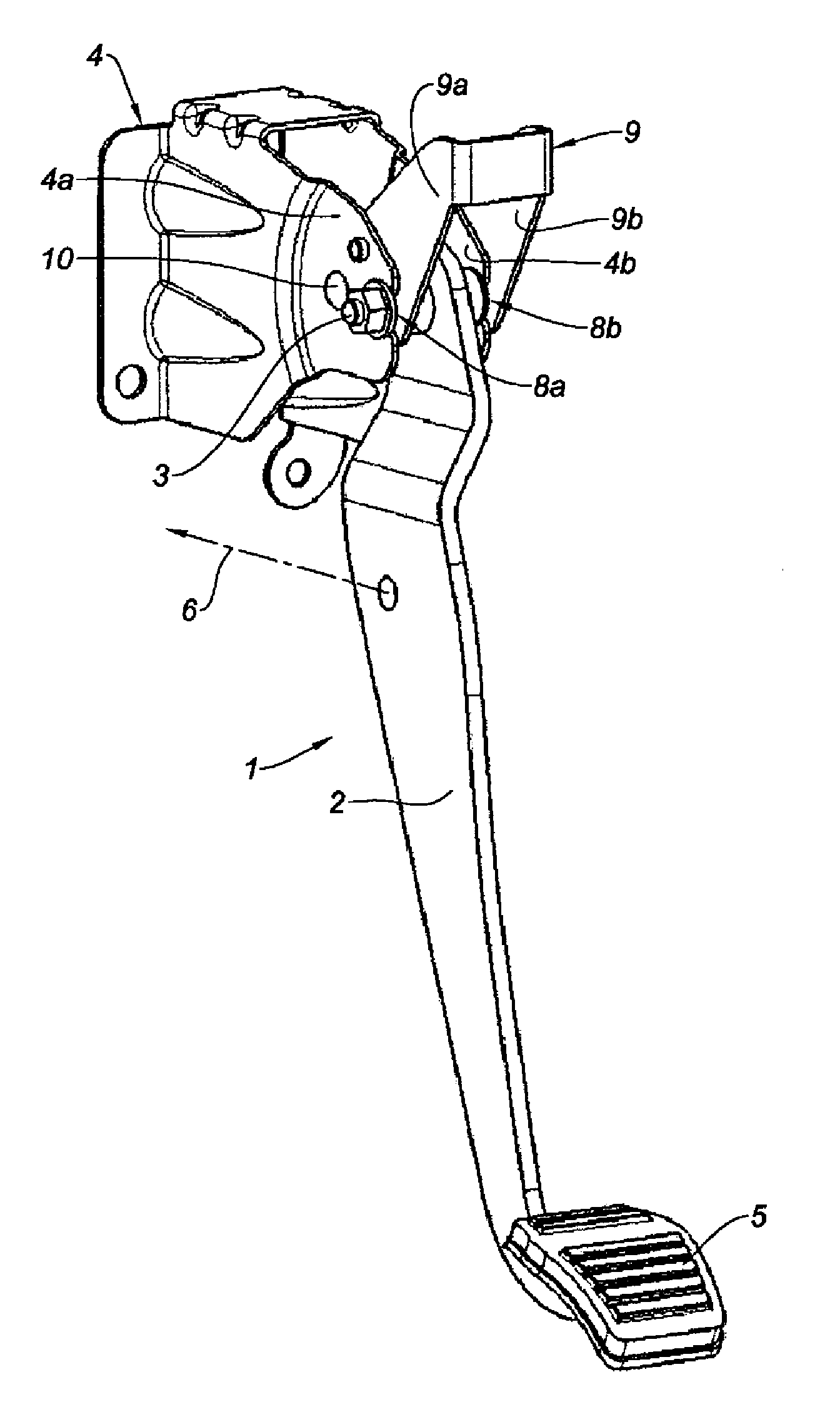
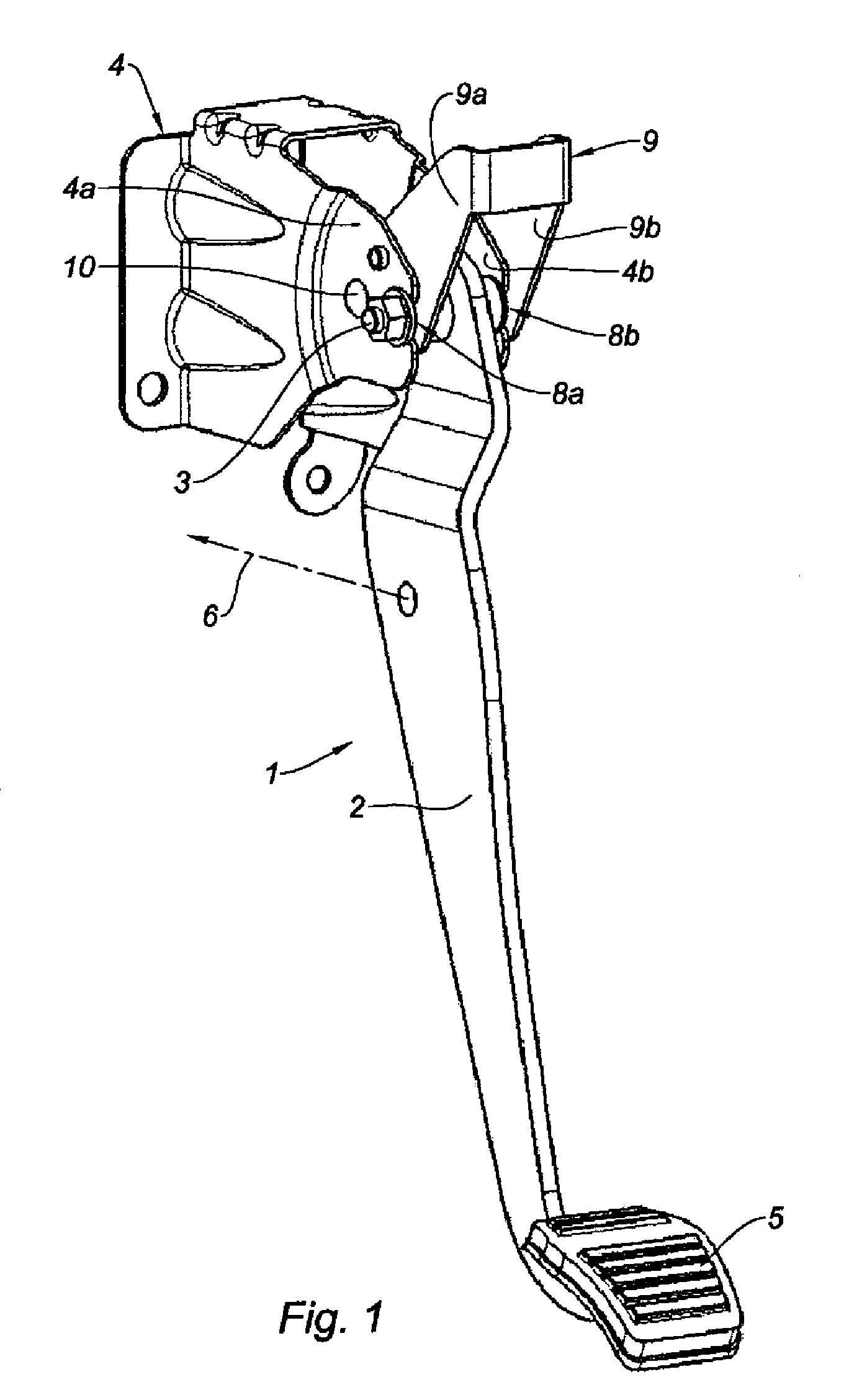
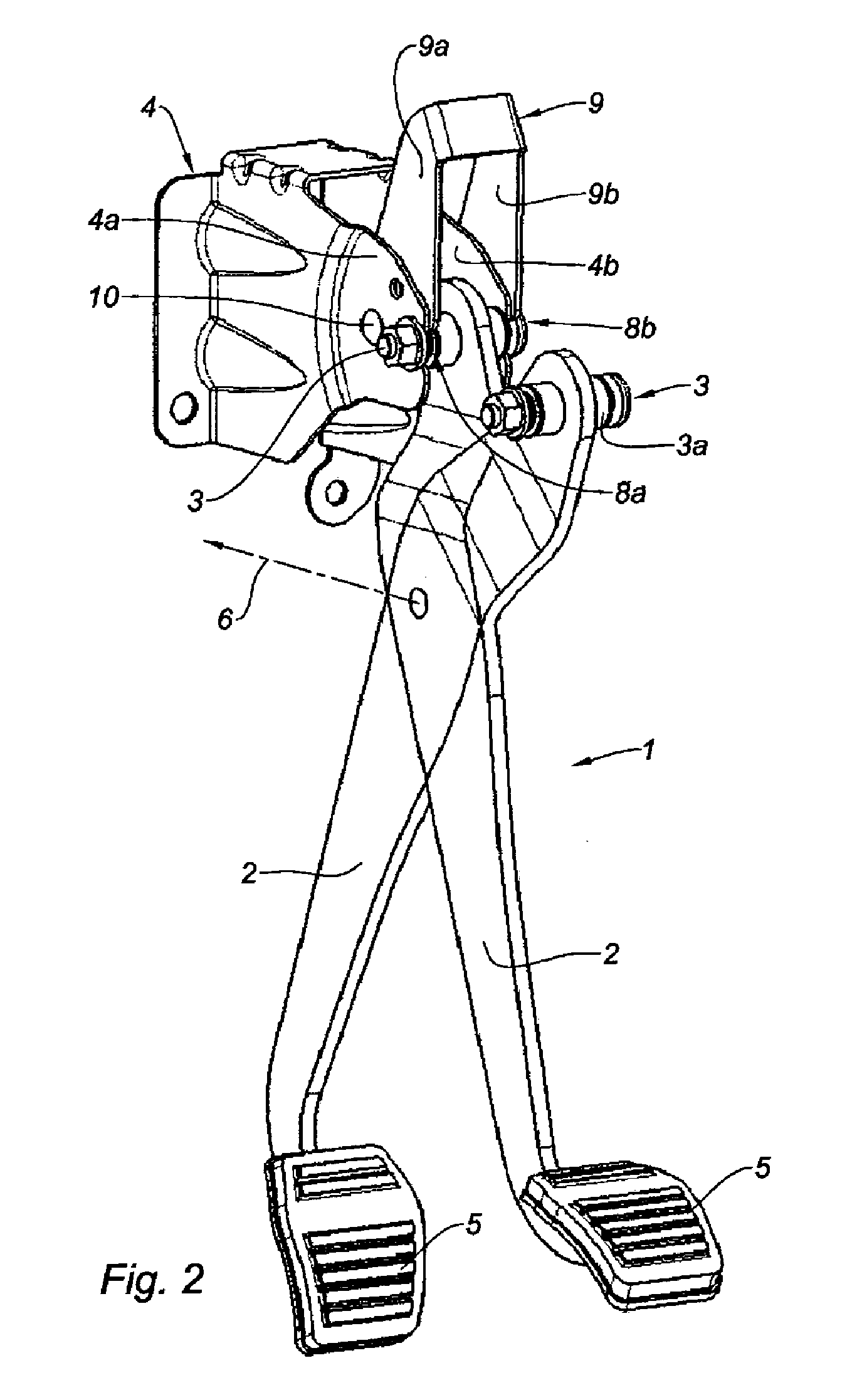
[0035]In reference to the drawing, a motor vehicle pedal 1 includes a pedal body 2 that, during normal operation of the pedal, pivots around a horizontal axis of rotation 3 relative to a pedal bracket 4, installed in a fixed position in the concerned motor vehicle. The lower end of the pedal body 2 supports a shoe 5, which is the part by which the driver of the vehicle actuates the pedal 1 through bearing via his foot. The pedal body 2 thus constitutes a lever that, by pivoting around the shaft 3, can transmit a movement and a force to a transmission or control member, variable depending on the type of pedal and the control mode, with or without assistance for the force, said member being able to be an actuating rod as symbolized in 6.

[0036]The pedal body 2 can also be connected to the pedal bracket 4 by a suitably guided return spring 7, which returns the shoe 5 to its idle position, when it is no longer pushed in by the driver's foot.

[0037]The pedal bracket 4 includes two parallel...


PUM


Abstract

The pedal is provided with a safety device, which works so as to release this pedal in the event of the vehicle suffering a frontal impact. The pedal body (2) is mounted on a bracket (4) having two parallel vertical plates (4a, 4b), in which there are arranged parallel holding slots (8a, 8b) through which the pivoting shaft (3) of the pedal passes, the holding slots (8a, 8b) opening onto the rear edge of the plates (4a, 4b) and / or being flared to the rear. A lever (9) is provided which, in the event of an impact, pivots in engagement with the pivoting shaft (3) in order to release it until it emerges completely from the two holding slots (8a, 8b) or is no longer retained by the edges of these slots. The pedal is thus entirely released, that is to say disconnected from its bracket (4), and can then “fall”. This pedal may be a brake pedal or a clutch pedal.

Description

TECHNICAL FIELD[0001]The present invention generally relates to pedals installed in the driver's area of a motor vehicle, such as brake and clutch pedals. More particularly, this invention pertains to one such motor vehicle pedal that is provided with a safety device, coming into play in the event of an impact suffered by the vehicle and in particular in case of frontal impact.BACKGROUND[0002]In a traditional design, a motor vehicle pedal, such as a brake pedal, is designed as a lever pivotably mounted around a substantially horizontal shaft, fixed relative to the structure of the vehicle.[0003]More recently, to satisfy the standards and other safety stipulations in case of impact, in particular frontal impact, suffered by a motor vehicle, pedals have appeared provided with a special mounting allowing, following an impact, a certain release of the pedal intended to prevent that pedal from causing injuries to the legs or feet of the concerned vehicle's driver. The solutions proposed ...

Claims


Application Information

Patent Timeline
Patent Type & Authority Patents(United States)
IPC IPC(8): G05G1/327
CPCB60R21/09B60T7/065G05G1/327Y10T74/20534Y10T74/20888
Inventor BLAIS, FREDERICFERRETTE, ERICGUEVELBADOU, JACQUES
Owner AKWEL SA
Learn More