Liquid ejecting head

a liquid ejector and head technology, applied in the direction of separation process, printing, filtration separation, etc., can solve the problems of clogging the filter, increasing the size of the ink-jet head in the horizontal plane, and reducing the effective surface area of the filter, so as to increase the ink flow resistance of the filter, reduce the effective surface area, and reduce the effect of the rate of ink flow

Active Publication Date: 2013-11-26
BROTHER KOGYO KK
View PDF22 Cites 0 Cited by
  • Summary
  • Abstract
  • Description
  • Claims
  • Application Information

AI Technical Summary

Benefits of technology

[0007]The reservoir unit described above suffers from another problem, that is, a problem of clogging of the filter with the captured foreign matters scattered over a comparatively large surface area in the horizontal plane. The clogging of the filter leads to a decrease in the effective surface area of the filter (surface area effective to capture the foreign matters), an increase in the ink flow resistance of the filter, and a consequent decrease of the rate of flow of the ink to the nozzles of the ink-jet head, eventually resulting in a failure of normal ejection of the ink from the nozzles. Since the filter is likely to be clogged over the relatively large surface area as described above, an ink circulation purging operation of the ink-jet head to cause positive flows of the ink along the filtering surface of the filter should be performed frequently, so that the efficiency of a printing operation of the ink-jet head tends to be lowered.
[0008]The present invention was made in view of the background art described above. It is therefore an object of the present invention to provide a liquid ejecting head which is configured to reduce its size in the horizontal plane and to reduce a chance of clogging of its filter with the foreign matters over a large surface area.

Problems solved by technology

The filter unit having the filter disposed so as to extend horizontally as described above tends to have a relatively large size in the horizontal plane if the filter is formed to have the cross sectional surface area large enough to effectively perform its filtering function to capture foreign matters such as air bubbles contained in the ink, and accordingly results in an undesirable increase in the size of the ink-jet head in the horizontal plane.
The reservoir unit described above suffers from another problem, that is, a problem of clogging of the filter with the captured foreign matters scattered over a comparatively large surface area in the horizontal plane.
The clogging of the filter leads to a decrease in the effective surface area of the filter (surface area effective to capture the foreign matters), an increase in the ink flow resistance of the filter, and a consequent decrease of the rate of flow of the ink to the nozzles of the ink-jet head, eventually resulting in a failure of normal ejection of the ink from the nozzles.

Method used


Image

  • Liquid ejecting head
  • Liquid ejecting head
  • Liquid ejecting head

Examples


Embodiment Construction

[0020]The preferred embodiment of this invention will be described by reference to the accompanying drawings.

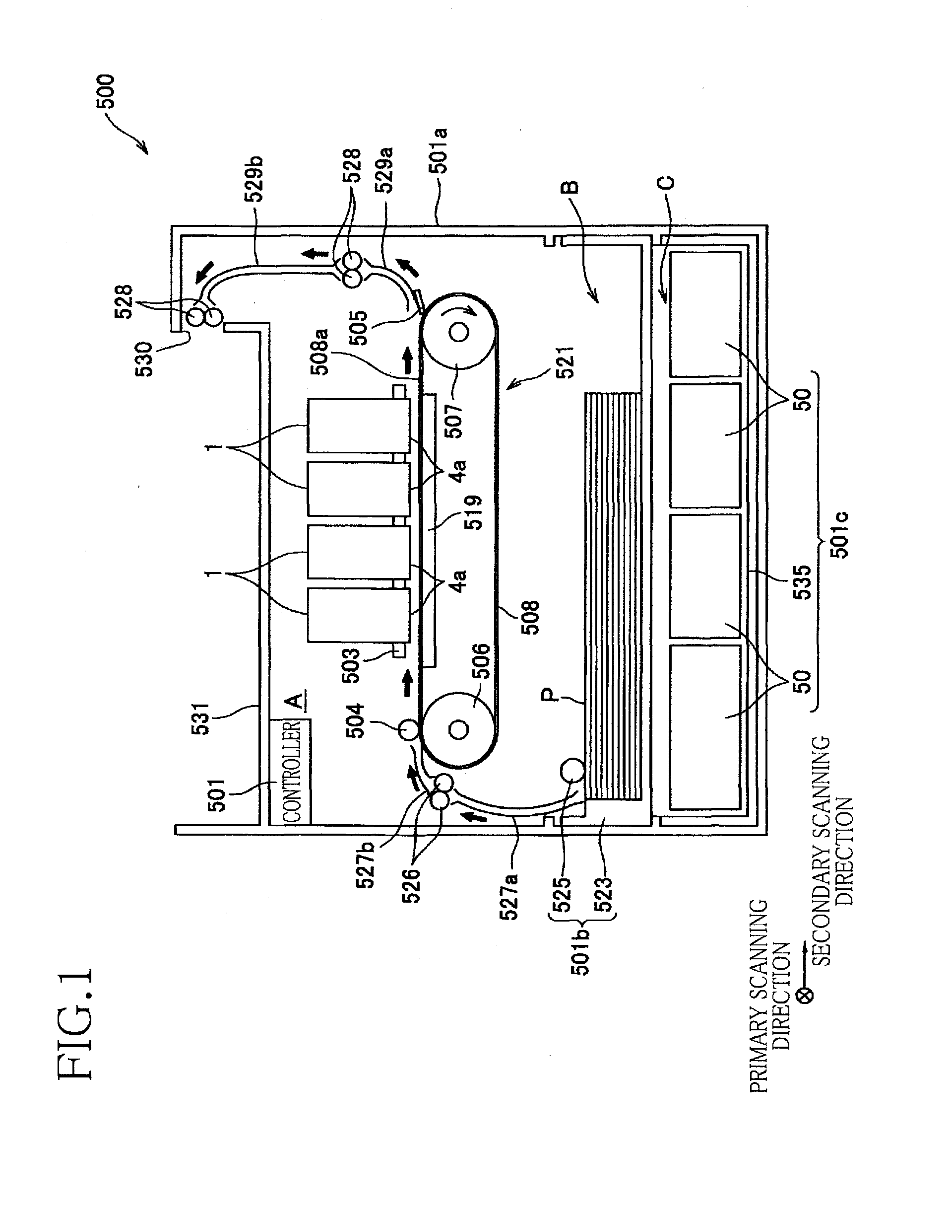
[0021]Referring first to the schematic side elevational view of FIG. 1, there is shown a printer 500 of an ink-jet type including four ink-jet heads 1 each constructed as a liquid ejecting head constructed according to the preferred embodiment of the present invention. Each of the ink-jet heads 1 is a so-called “line printing head” disposed so as to extend in one direction (direction perpendicular to the plane of the view of FIG. 1). That is, each ink-jet head 1 has its longitudinal direction that is a primary scanning direction, which is perpendicular to a secondary scanning direction in which the four ink-jet heads 1 are arranged in the ink-jet printer 500 of the line printing type.

[0022]The printer 500 has a housing 501a in the form of a generally rectangular parallelepiped having a top wall that serves as a sheet receiver 531. The housing 501a has three functional spaces ...


PUM

PropertyMeasurementUnit
angle of inclination θ4aaaaaaaaaa
angle of inclination θ8aaaaaaaaaa

Abstract

A liquid ejecting head having a liquid-flow space through which a liquid flows from a liquid supply source toward liquid-drop ejecting nozzles, a generally planar partition portion extending in a direction intersecting a vertical direction and partially defining the liquid-flow space, and further partially defining first and second chambers such that the two chambers are arranged in a horizontal direction on respective opposite sides of the partition wall, the first and second chambers having a larger dimension in the vertical direction than in the horizontal direction, in cross section taken in a plane parallel to the vertical direction and a direction of arrangement of the two chambers, and a planar filter fixed to the partition portion so as to extend in a direction intersecting the horizontal direction, along a surface of the partition portion and configured to capture foreign matters contained in the liquid in at least one of the two chambers.

Description

CROSS REFERENCE TO RELATED APPLICATION[0001]The present application claims the priority from Japanese Patent Applications No. 2010-029799 filed Feb. 15, 2010, the disclosure of which is herein incorporated by reference in its entirety.BACKGROUND OF THE INVENTION[0002]1. Field of the Invention[0003]The present invention relates to a liquid ejecting head configured to eject droplets of a liquid such as an ink.[0004]2. Description of Related Art[0005]There is known an ink-jet head as an example of a liquid ejecting head, which includes a reservoir unit that temporarily stores an ink to be supplied from an ink tank and delivered to ink-ejecting nozzles. This reservoir unit includes a horizontally extending film, an inlet joint formed at one end of the film, and a filter disposed so as to extend in parallel to the film, and has a reservoir passage, a central communication hole in communication with the reservoir passage, and ink flow passages formed such that the ink which has entered in...

Claims


Application Information

Patent Timeline
Patent Type & Authority Patents(United States)
IPC IPC(8): B41J2/175
CPCB41J2/17563
Inventor ITO, TAKASHI
Owner BROTHER KOGYO KK
Why Eureka
Try Eureka