
Fuel cell-use catalyst electrode and fuel cell having this catalyst electrode, and production methods therefor

a technology of catalyst electrode and fuel cell, which is applied in the direction of cell components, final product manufacturing, sustainable manufacturing/processing, etc., can solve the problems of reducing output power, affecting the supply of fuel, and reducing power generation efficiency and catalyst effective surface area, so as to prevent the decrease of fuel electrode output power, reduce the effect of fuel electrode effective surface area and avoiding the effect of foaming air

Inactive Publication Date: 2006-05-25
NEC CORP
View PDF1 Cites 0 Cited by
  • Summary
  • Abstract
  • Description
  • Claims
  • Application Information

AI Technical Summary

Benefits of technology

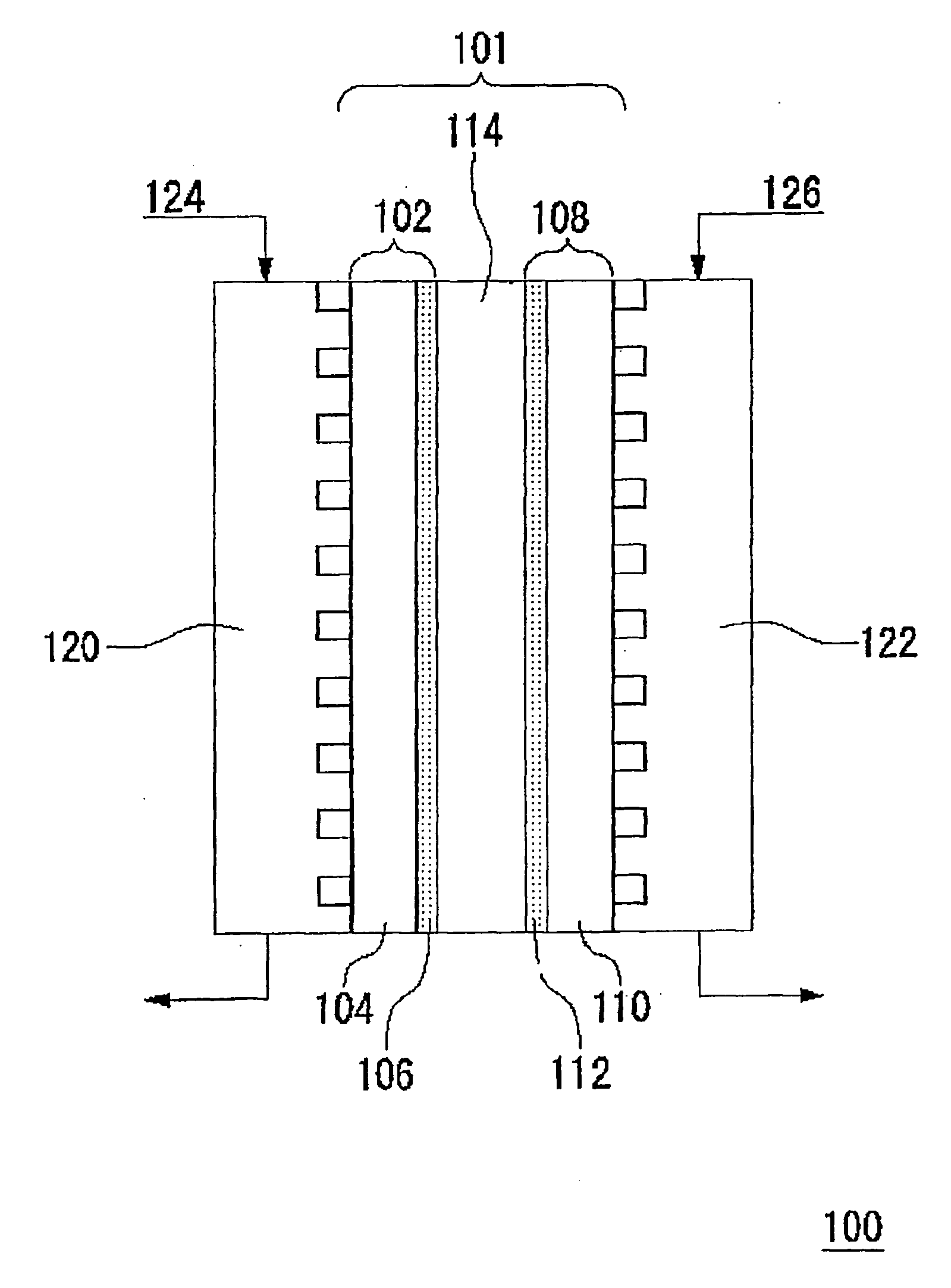
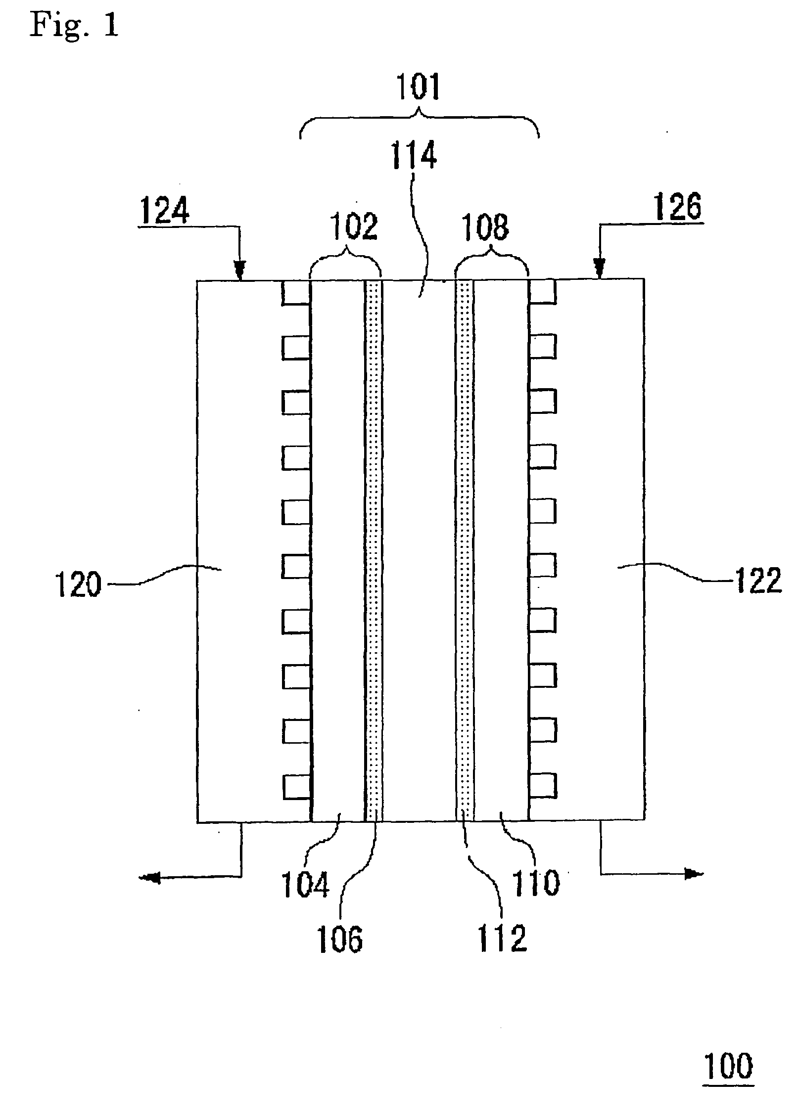
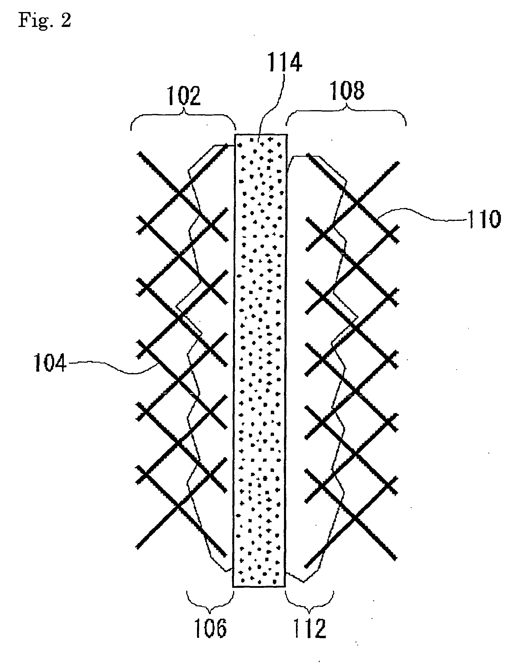
The present invention relates to a catalyst electrode for a fuel cell that includes a substrate and a catalyst layer containing a carbon particle and a solid polymer electrolyte, with an anti-foaming agent added to at least one of the substrate or the catalyst layer. The anti-foaming agent prevents the adsorption of air bubbles generated by a reaction at the fuel electrode, which helps to maintain the effective surface area of the electrode and prevent a decrease in output power. The anti-foaming agent can be selected from a variety of chemicals, such as fatty acids, fatty acid esters, alcohols, ether-based compounds, phosphates, amines, amides, metals, sulfates, silicones, mineral oils, polypropylene glycols, low-molecular-weight polyethylene glycols, and others. The addition of the anti-foaming agent to both the substrate and the catalyst layer further enhances the suppression of air bubble adsorption and increases the effective surface area of the fuel electrode. The fuel cell using this catalyst electrode has a high output power. The manufacturing method of the catalyst electrode involves forming a catalyst layer on a substrate coated with a solution containing a conductive particle carrying a catalyst, a particle of a solid polymer electrolyte, and at least one kind of anti-foaming agent.

Problems solved by technology

In a conventional direct methanol fuel cell, carbon dioxide generated in accordance with the chemical equation [1] a carbon monoxide which is an intermediate product in the chemical equation [1] is collected in the pores of the fuel electrode, and thus hinders supply of the fuel.
Accordingly, power generation efficiency and an effective surface area of the catalyst decrease, whereby output power is reduced.

Method used


Image

  • Fuel cell-use catalyst electrode and fuel cell having this catalyst electrode, and production methods therefor
  • Fuel cell-use catalyst electrode and fuel cell having this catalyst electrode, and production methods therefor
  • Fuel cell-use catalyst electrode and fuel cell having this catalyst electrode, and production methods therefor

Examples


example 1

From Example 1 and Comparative Example 1, it was confirmed that the catalyst electrode according to this example has an effect of preventing adsorption of air bubbles on the surface thereof and of quickly removing them.

example 2

[0098] A fuel cell was prepared using the catalyst electrode in Example 1 as a fuel electrode, and the catalyst electrode in Comparative Example 1 as an oxidant electrode. Specifically, the fuel electrode and the oxidant electrode were pressure-bonded on respective sides of Nafion 117 Membrane (manufactured by DuPont: registered trademark) at 120° C., and the obtained catalyst electrode-solid electrolyte membrane assembly was used as a cell for the fuel cell.

[0099] 30 v / v % methanol solution and oxygen were respectively supplied to the fuel electrode and the oxidant electrode of the obtained cell of the fuel cell at a cell temperature of 60° C. The flow rates of the 30 v / v % methanol solution and the oxygen were 100 ml / min and 100 ml / min, respectively. The voltage-current characteristic when each fuel was supplied was evaluated using a cell performance evaluation apparatus.

The result as shown in Table 2 was obtained on the fuel cells of which the fuel electrodes contain individua...

example 3

[0102] A catalyst electrode was prepared by further adding polyethylene glycol diester laurate as a mixing accelerator and stabilizer of the anti-foaming agent, when the catalyst paste in Example 1 was prepared and when pretreatment was provided on the carbon paper. The surface of the catalyst electrode was observed using a scanning electron microscope and EMMA.

[0103] As a result, it was confirmed that particles of the anti-foaming agent were dispersed more finely on the electrode catalyst prepared in this example compared to the electrode catalyst prepared in Example 1. Using the thus obtained catalyst electrode as a fuel electrode, the voltage-current characteristic was evaluated as in the same manner as Example 2.

The result as shown in Table 3 was obtained on the fuel cells of which the fuel electrodes contain individual anti-foaming agents.

[0104] Table 3 showed that the output power of the fuel cell was further increased by using a catalyst electrode to which polyethylene gl...


PUM

PropertyMeasurementUnit
particle diameteraaaaaaaaaa

Abstract

The present invention provides a catalyst electrode and a manufacturing method of the same. When the catalyst electrode is used for a fuel cell, it is capable of suppressing an air, which is a by-product generated at a fuel electrode on a surface of the electrode, and quickly removing the adsorbed bubble-like air. Accordingly, the catalyst electrode is capable of increasing an effective catalyst surface of the fuel electrode and enhancing an output power of the fuel cell. Moreover, the present invention provides fuel cell and a manufacturing method of the same. The fuel cell is capable of suppressing an air, which is a by-product generated at the fuel electrode on the surface of the electrode and quickly removing the adsorbed bubble-like air. Accordingly, the fuel cell is capable of increasing an effective catalyst surface of the fuel electrode and enhancing an output power thereof. In a catalyst electrode for a fuel cell provided with a substrate and a catalyst layer which is formed on the substrate and which contains a carbon particle carrying a catalyst and a solid polymer electrolyte, the substrate or the catalyst layer contains one or more kinds of anti-foaming agent.

Description

TECHNICAL FIELD [0001] The present invention relates to a catalyst electrode for a fuel cell of a type which directly supplies a battery with a fuel composed of hydrogen and carbon, as well as to a fuel cell having the catalyst electrode for a fuel cell and manufacturing methods of them. [0002] For the purpose of sufficiently explaining the current level of the art related to the present invention, descriptions of all patents, patent applications, patent gadgets, scientific literatures and the like quoted or specified herein are incorporated herein by reference in its entirety. BACKGROUND OF THE ART [0003] A solid electrolyte-type fuel cell is a device configured by respectively bonding a fuel electrode and an oxidant electrode on a side of a solid electrolyte membrane such as a perfluorosulfonic acid membrane or the like which is used as an electrolyte. This device generates electric power based on an electrochemical reaction supplying hydrogen and methanol for the fuel electrode a...

Claims


Application Information

Patent Timeline
Patent Type & Authority Applications(United States)
IPC IPC(8): H01M4/86H01M4/02H01M4/88H01M8/06H01M8/10
CPCH01M4/8605H01M4/8663Y02E60/521H01M4/8896H01M8/1004H01M4/8828Y02P70/50Y02E60/50
Inventor IMAI, HIDETOYOSHITAKE, TSUTOMUSHIMAKAWA, YUICHIMANAKO, TAKASHINAKAMURA, SHINKIMURA, HIDEKAZUKUROSHIMA, SADANORIKUBO, YOSHIMI
Owner NEC CORP
Learn More