This helps you quickly interpret patents by identifying the three key elements:
Problems solved by technology
Method used
Benefits of technology
[0021]Moreover, it provides such an electronic image display system wherein such unitary housing comprises at least one adjuster adapted to adjust such unitary housing to situate such at least one first electronic image display screen and such at least one second electronic image display screen essentially parallel with a partition wall having at least one respective first side and at least one opposing second side. Additionally, it provides such an electronic image display system wherein such at least one image display controller further comprises: at least one parent controller adapted to assist at least one parent control of such operable display of at least one electronic image derived from the at least one electronic image signal.
[0022]Also, it provides such an electronic image display system wherein such at least one image display controller further comprises: at least one child controller structured and arranged to restrict access of at least one portion of the at least one electronic image signal; wherein such child control is restricted by at least such at least one parent controller. In addition, it provides such an electronic image display system wherein such at least one parent controller further comprises at least one image display selector structured and arranged to select the at least one electronic image signal to be displayed on at least one of such at least one first electronic image displayer and such at least one second electronic image displayer. And, it provides such an electronic image display system wherein such at least one image display selector further comprises at least one selective switch structured and arranged to selectively switch at least one portion of the at least one electronic image from such at least one first electronic image display screen to such at least one second electronic image display screen.
Problems solved by technology
For security purposes these televisions are often “locked” into expensive casings and their electrical connections are often “secured” by expensive connectors.
Method used
Image
Click on the blue label to locate the original text in one second.
Reading with bidirectional positioning of images and text.
Examples
Embodiment Construction
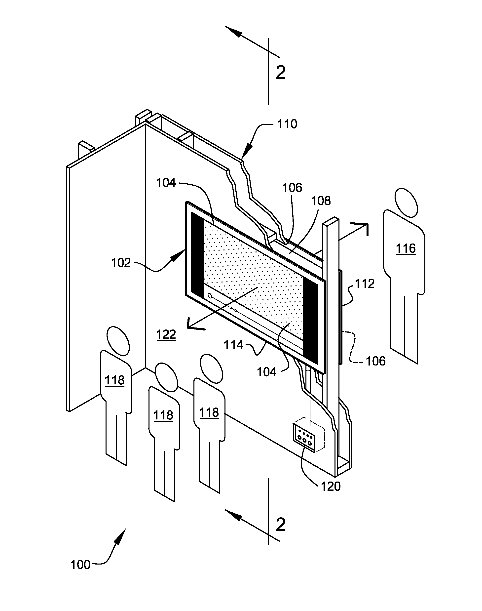
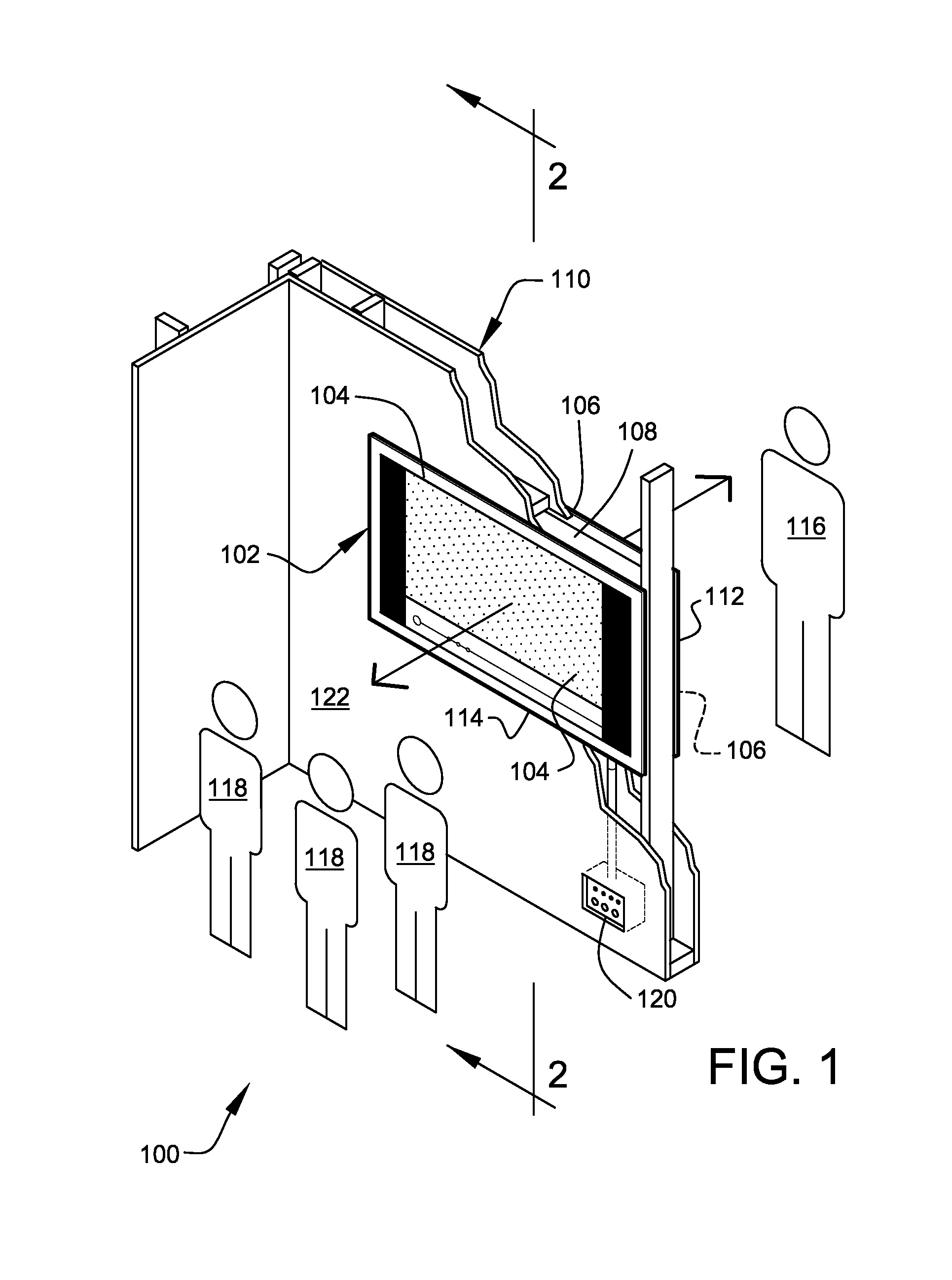
[0036]FIG. 1 shows a perspective view of the electronic image display system 100 according to a preferred embodiment of the present invention. Preferably, the electronic image display system 100 comprises a unitary back-to-back display 102, preferably as shown. Preferably, the unitary back-to-back display 102 comprises a first side 104 and a second side 106, preferably mounted in a single housing 108, as shown. Upon reading the teachings of this specification, those of ordinary skill in the art will now understand that, under appropriate circumstances, considering such issues as intended use, design modifications, hardware available, consumer trends, etc., other image display systems having a back-to-back display orientation, such as, digital signage units, computer desktop monitors, laptop computers, electronic signs, electronic picture frames, video game monitors, cameras, handheld phones, mobile phones, portable media players with screens, other back-to-back image display systems...
PUM
Abstract
Dual display screens are oriented back-to-back such that one display screen is visible from a first direction and one display screen is visible from a direction opposite the first direction.
Description
CROSS-REFERENCE TO RELATED APPLICATIONS[0001]The present application is a continuation-in part of application Ser. No. 12 / 060,180, filed Mar. 31, 2008, entitled “ELECTRONIC IMAGE DISPLAY SYSTEMS”, which is a continuation of application Ser. No. 11 / 084,665, filed Mar. 18, 2005, entitled “ELECTRONIC IMAGE DISPLAY SYSTEMS”, now U.S. Pat. No. 7,352,415, issued Apr. 1, 2008, which is related to and claims priority from prior provisional application Ser. No. 60 / 565,143, filed Apr. 23, 2004, entitled “ELECTRONIC IMAGE DISPLAY SYSTEMS”, the contents of all of which are incorporated herein by this reference and are not admitted to be prior art with respect to the present invention by the mention in this cross-reference section.BACKGROUND[0002]This invention relates to providing useful arrangements of back-to-back display screens.[0003]Typically, electronic image display screens, such as computer monitors, television screens, laptop computer screens, etc., are single-sided or front-viewing-on...
Claims
Application Information
Patent Timeline
Application Date:The date an application was filed.
Publication Date:The date a patent or application was officially published.
First Publication Date:The earliest publication date of a patent with the same application number.
Issue Date:Publication date of the patent grant document.
PCT Entry Date:The Entry date of PCT National Phase.
Estimated Expiry Date:The statutory expiry date of a patent right according to the Patent Law, and it is the longest term of protection that the patent right can achieve without the termination of the patent right due to other reasons(Term extension factor has been taken into account ).
Invalid Date:Actual expiry date is based on effective date or publication date of legal transaction data of invalid patent.