Flexible door seal device

Active Publication Date: 2013-12-03
WELLS JOHN D
View PDF33 Cites 1 Cited by
  • Summary
  • Abstract
  • Description
  • Claims
  • Application Information

AI Technical Summary

Benefits of technology

[0016]Still another object of the flexible door seal device is to

Problems solved by technology

Sealing a door against air leaks has re

Method used


Image

  • Flexible door seal device
  • Flexible door seal device
  • Flexible door seal device

Examples


Example

DETAILED DESCRIPTION OF THE DRAWINGS

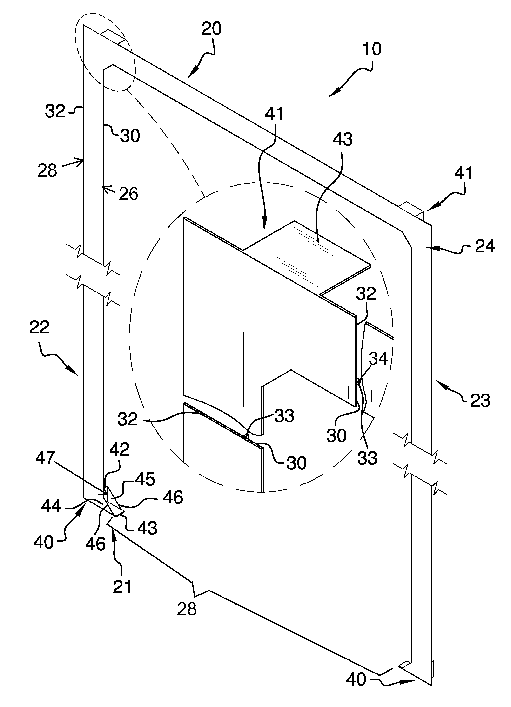
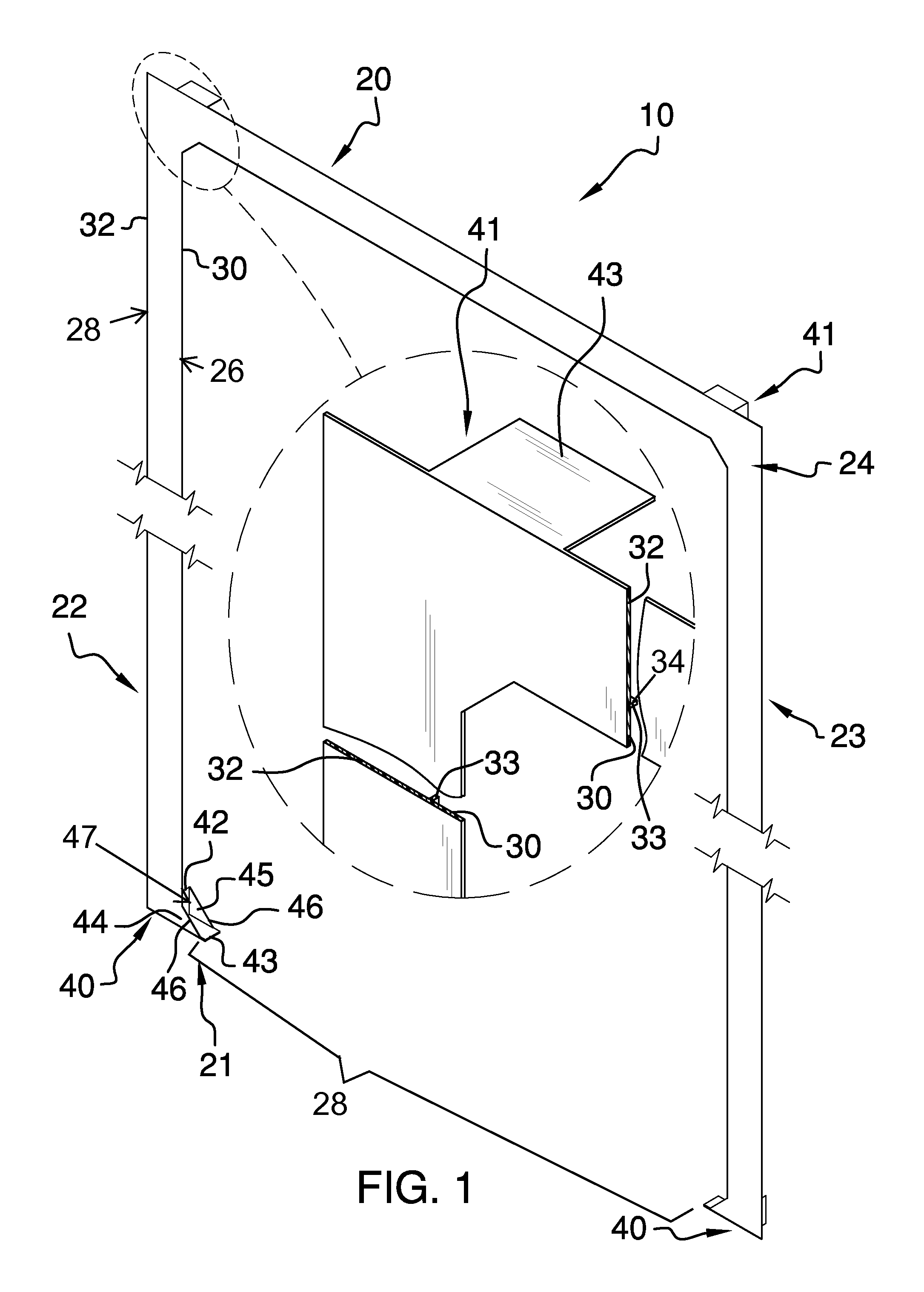
[0024]With reference now to the drawings, and in particular FIGS. 1 through 6 thereof, the principles and concepts of the flexible door seal device generally designated by the reference number 10 will be described.

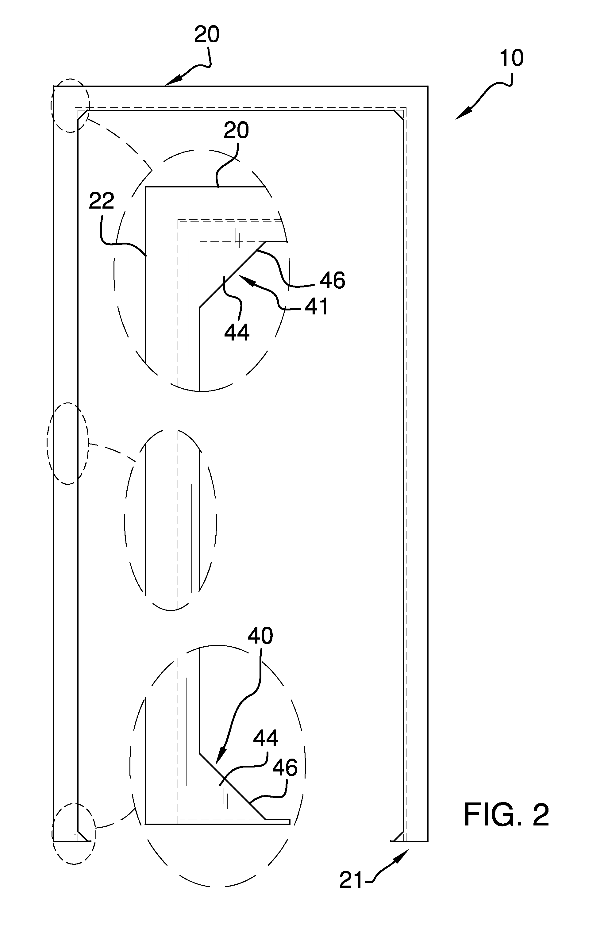
[0025]Referring to FIG. 1, the device 10 partially comprises a frame 19 having a top side 20 spaced apart from a bottom side 21, a first side 22 spaced apart from a second side 23. The bottom side 21 has a central opening 28.

[0026]Referring to FIG. 4, the frame 19 also has a front side 24 spaced apart from a back side 25, a continuous inner perimeter 26 and a continuous outer perimeter 27.

[0027]Referring again to FIG. 1, an inner flap 30 is continuously disposed along the inner perimeter 26 of the frame 19. An outer flap 32 is continuously disposed along the outer perimeter 27 of the frame 19.

[0028]Referring to FIG. 5 and again to FIG. 1, a T-shaped insert 33 has a rear portion 34 extended from the front side 24 toward the back side 25 a...


PUM

PropertyMeasurementUnit
Sizeaaaaaaaaaa
Flexibilityaaaaaaaaaa

Abstract

The flexible door seal device provides for sealing against air leaks around a door and doorway without interfering with door opening and closing. The flexible device is easily installed and removed without need of any tools. Also, the device can be rolled or folded into a compact size for transport and storage as needed. The device is self-retained until removed from a door. Retention is accomplished by way of the pockets disposed at each corner. Ideally, the device may be seamless. The device provides a positive seal by way of the insert and the inner flap and outer flap that overlap any space between a door and a jamb. The outer flap is sufficient to overlap drywall, trim, and other door surrounds.

Description

CROSS-REFERENCE TO RELATED APPLICATIONS[0001]Not ApplicableFEDERALLY SPONSORED RESEARCH OR DEVELOPMENT[0002]Not ApplicableINCORPORATION BY REFERENCE OF MATERIAL SUBMITTED ON A COMPACT DISK[0003]Not ApplicableBACKGROUND OF THE INVENTION[0004]Sealing a door against air leaks has remained a challenge throughout the years. Various devices have been attempted to address the problem. The current removable, flexible device provides a positive seal against air leaks around the side, top and corners of a door.FIELD OF THE INVENTION[0005]The flexible door seal device relates to devices for sealing doors against air leaks.SUMMARY OF THE INVENTION[0006]The general purpose of the flexible door seal device, described subsequently in greater detail, is to provide a flexible door seal device which has many novel features that result in an improved flexible door seal device which is not anticipated, rendered obvious, suggested, or even implied by prior art, either alone or in combination thereof.[00...

Claims


Application Information

Patent Timeline
IPC IPC(8): E06B7/16
CPCE06B7/23
Inventor WELLS, JOHN D.
Owner WELLS JOHN D
Why Eureka
Try Eureka