
Canopy system and group suspension system therefore

a suspension system and canopy technology, applied in the field of canopies, can solve the problem of adding cost to the system, and achieve the effect of reducing the number of attachment points and facilitating installation

Active Publication Date: 2013-12-03
AWI LICENSING
View PDF31 Cites 31 Cited by
  • Summary
  • Abstract
  • Description
  • Claims
  • Application Information

AI Technical Summary

Benefits of technology

The improved canopy system has several benefits. Firstly, it allows for easy access from below. Secondly, it uses a safe and secure suspended system that complies with seismic codes. Thirdly, it allows for multiple canopies to be installed close to each other. Fourthly, it is easy to install and align. Finally, it reduces the number of attachment points to the overhead building structure by 25-50%.

Problems solved by technology

Additionally, irrespective of the level of seismic activity, there are additional installation concerns, including concerns regarding alignment and registration of canopies when grouped together in the ceiling space.
Alignment and registration are currently achieved through careful installation which is time consuming, which, in turn, adds cost to the system.

Method used


Image

  • Canopy system and group suspension system therefore
  • Canopy system and group suspension system therefore
  • Canopy system and group suspension system therefore

Examples


Embodiment Construction

[0018]Referring now in greater detail to the figures, wherein like numerals refer to like parts throughout the drawings.

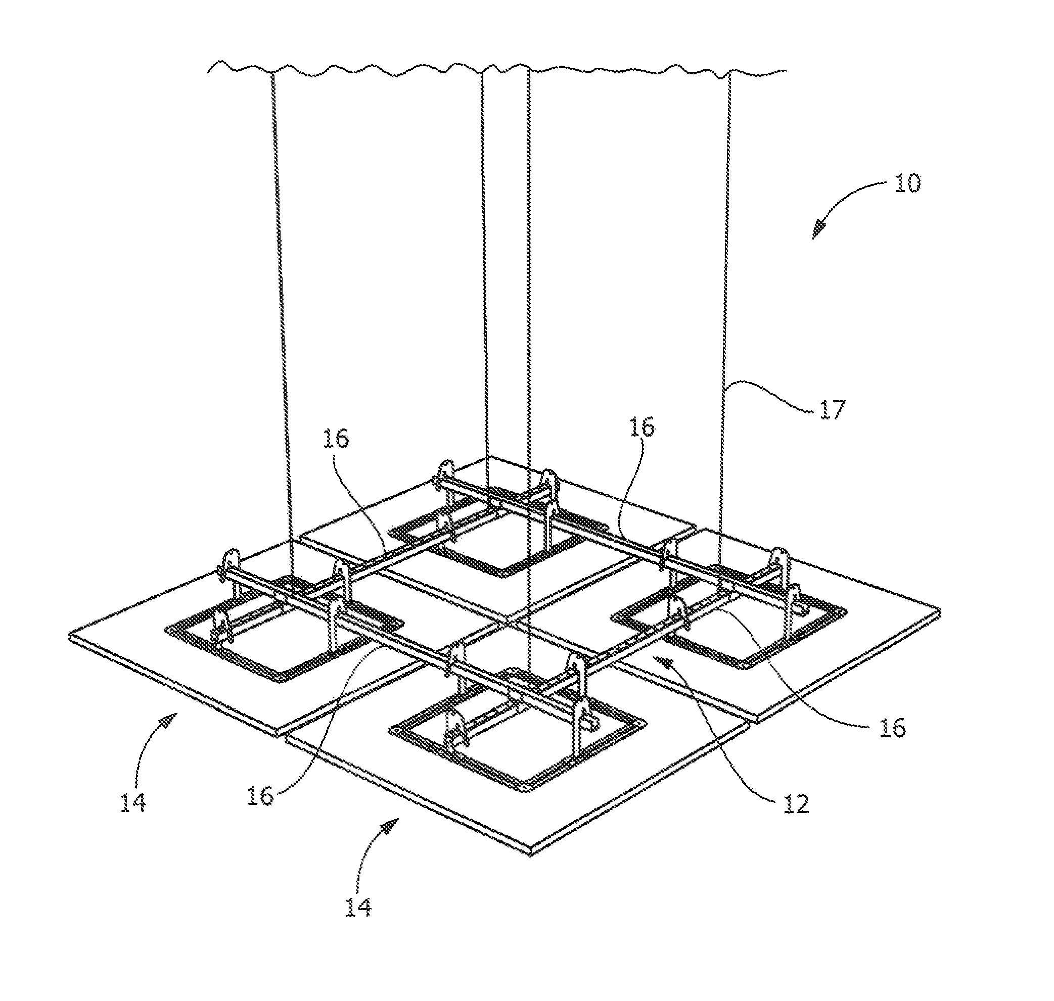
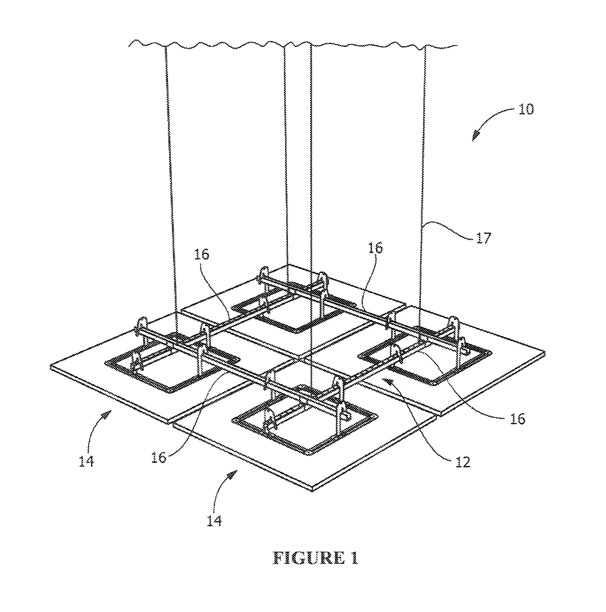
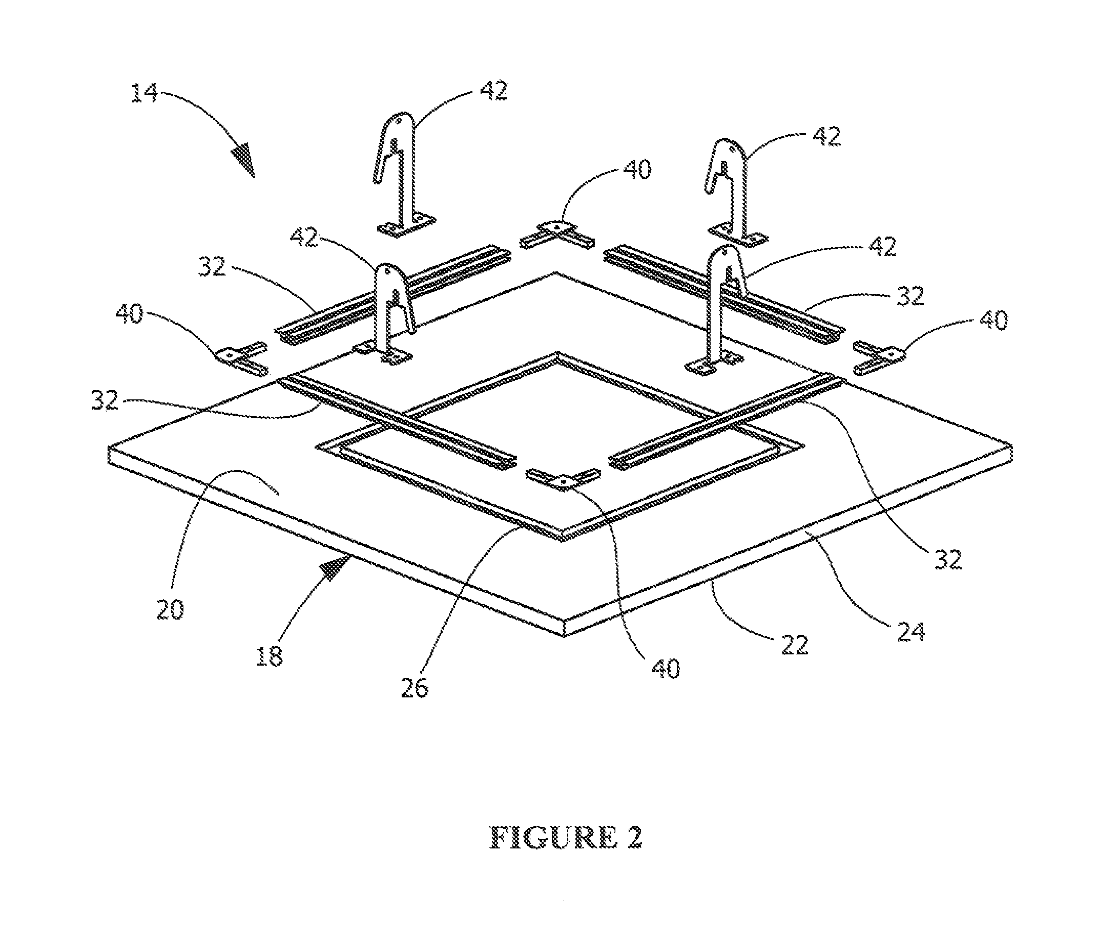
[0019]FIGS. 1 and 2 illustrate the general structural arrangement of an example embodiment of the canopy system of the invention. The canopy system 10 includes a grouping frame 12 and one or more canopy modules 14. The grouping frame 12 has at least two intersecting struts 16 which are attached to one another and are supported by the overhead building structure (not shown) by a hanging device, such as the suspension cables 17 shown in FIG. 1.

[0020]As best seen on FIG. 2, the canopy module 14 has a panel 18, such as a fibrous acoustical panel or wood panel, which has a top surface 20, a bottom surface 22 and an edge 24 extending therebetween. The panel 18 includes a routed in-board channel 26 which extends from the top surface 20 in a direction toward the bottom surface 22. For purposes of this description, the term “in-board channel” refers to a channel that does n...


PUM


Abstract

A canopy system for use in the interior building environment. The canopy system of the invention meets seismic code requirements and includes a group suspension system for mechanically aligning and registering canopy modules relative one another. The system requires a minimum number of attachment points to the overhead building structure.

Description

CROSS REFERENCE TO RELATED APPLICATION[0001]This application claims the benefit under 35 U.S.C. §119(e) of U.S. provisional application Ser. No. 60 / 933,803, filed Jun. 8, 2007.BACKGROUND OF THE INVENTION[0002]The present invention is directed to a canopy system, and, more particularly, a canopy system which provides mechanical alignment and registration of the canopy modules when grouped together.[0003]Exposed structure types of spaces which utilize suspended ceiling islands or ceiling canopies are in increasing demand. Such systems provide architects and designers with the ability to create unique and dramatic visual effects not available with continuous, wall-to-wall ceiling systems.[0004]For aesthetic purposes, it is desirable for the ceiling canopies to have clean, finished edges free of any exposed, unsightly edge detail or fastening means. One solution for providing this desired edge detail is shown and described in U.S. Patent Application Publication No. 2007 / 0033902, entitle...

Claims


Application Information

Patent Timeline
Patent Type & Authority Patents(United States)
IPC IPC(8): E04B2/00
CPCE04B9/0464E04B9/225E04B9/18E04B9/34E04B9/28E04B9/04E04B9/067E04B9/10
Inventor WATERS, JAMES R.RINEER, JAMES P.SPRINGER, BRIAN L.FRANTZ, WILLIAM H.
Owner AWI LICENSING
Learn More