Suturing needle

a suturing needle and needle body technology, applied in the field of suturing needles, can solve the problems of insufficient suturing needle transmission of high thrust, and achieve the effect of reducing deformation and high resistan

Active Publication Date: 2013-12-03
MATSUTANI SEISAKUSHO CO LTD
View PDF6 Cites 2 Cited by
  • Summary
  • Abstract
  • Description
  • Claims
  • Application Information

AI Technical Summary

Benefits of technology

[0011]An object of the present invention is to provide a suturing needle, which can be reliably held by a needle holder, which can transmit a high thrust, and which can reduce the risk of damaging an operator, and the deformation when a strong force acts.
[0013]R of the convex portion of the holding face of the needle holder is smaller and sharper than R3. If the angles of R3 and the convex portion are the same, the convex portion makes a point contact with the bottom portion of R3. The holdability becomes poor. For the suturing needle manufacturing method, the roundness of the valley cannot be eliminated so that the angle of the convex portion is smaller. R2 (the roundness of the crest) is equal to or larger than R3. R2 does not deeply enter into the concave portion of the holding face of the needle holder. The convex portion can relatively deeply enter into R3 and is brought into contact with the large area of R3. The holdability becomes good. R1 (the radius of the peak as the joint portion between the flat faces) is equal to or larger than R3. The convex portion can easily enter into R3.
[0020]The needle tip is formed to be rounded or flat blunt. The suturing needle cannot damage the glove or skin of the operator. A force applied when the blunt needle tip pierces the tissues acts in the direction of opening the curve. However, the trunk portion has a triangular section in which the peak is arranged on the outer circumferential side of the curve and the face is arranged on the inner circumferential side of the curve. Thus, the limited sectional area can be effectively used to exhibit high resistance relative to the acting bending force, thereby reducing deformation.

Problems solved by technology

However, according to the position of the rib(s) formed in the plane region, the suturing needle is rotated when being originally held by the needle holder and the transmission of a high thrust to the suturing needle is not sufficient.

Method used


Image

  • Suturing needle
  • Suturing needle
  • Suturing needle

Examples


embodiment 1

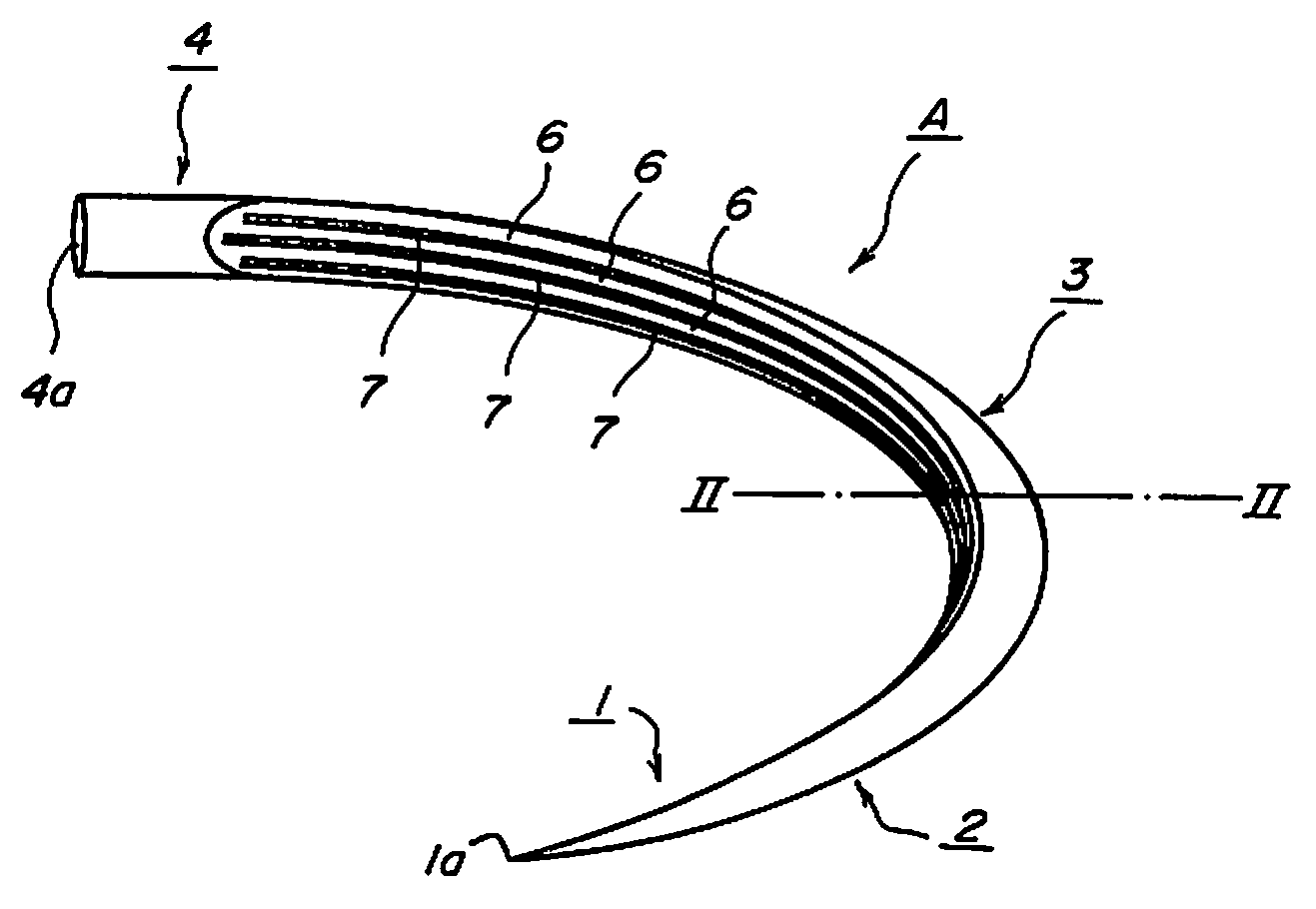
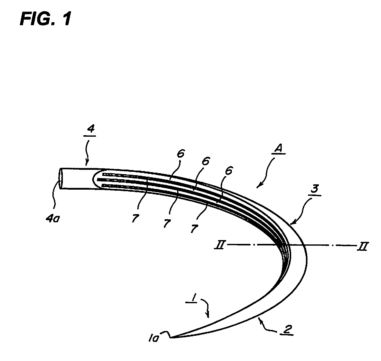
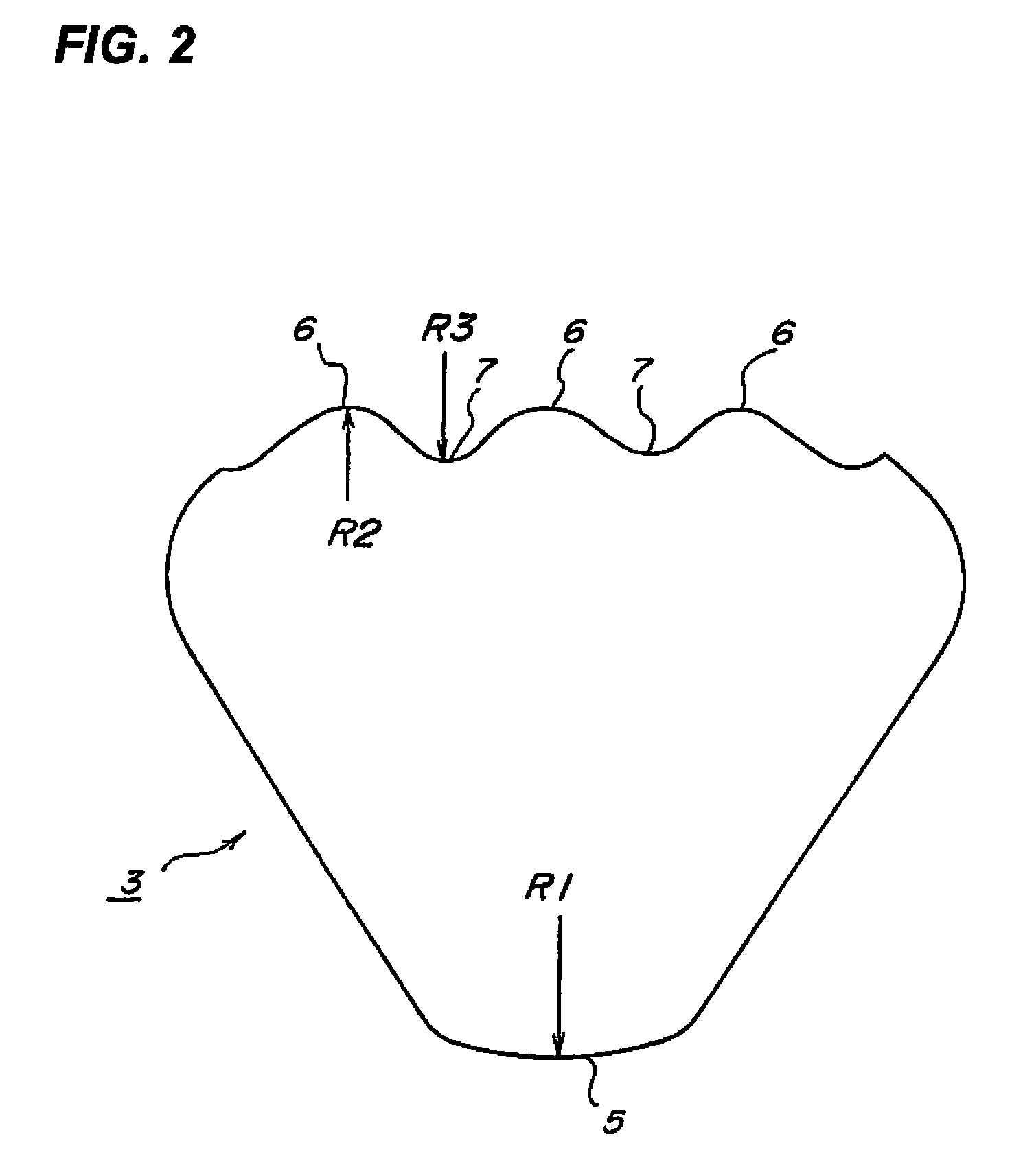
[0062]An embodiment of a suturing needle of the present invention will be described below with reference to the drawings. FIG. 1 is a perspective view of a curved suturing needle. FIG. 2 is a cross-sectional view of a trunk portion of the suturing needle. FIG. 3 is a diagram of assistance in explaining a mold for molding the suturing needle and a molded state. FIG. 4 is a diagram of assistance in explaining an intermediate member before the suturing needle is curved. FIGS. 5A, 5B, 5C, and 5D are diagrams of assistance in explaining examples of the shapes of a needle tip and a needle tip portion.

[0063]An illustrated suturing needle A has a needle tip portion 1, a tapered portion 2 continuing to the needle tip portion 1, a trunk portion 3 continuing to the tapered portion 2, and a thread attaching portion 4 continuing to the trunk portion 3. The suturing needle A is a curved needle formed so that the entire suturing needle is curved from the needle tip portion 1 to the thread attachin...


PUM

PropertyMeasurementUnit
diameteraaaaaaaaaa
thicknessaaaaaaaaaa
diameteraaaaaaaaaa

Abstract

A suturing needle, comprising needle tip portion (1) having needle tip (1a), tapered portion (2) continuing to needle tip portion (1), trunk portion (3) continuing to tapered portion (2), and thread attaching portion (4) continuing to trunk portion (3); needle tip portion (1) has circular section continuing to sharp needle tip (1a), angular section continuing to sharp needle tip (1a), circular section continuing to blunt needle tip (1a) or angular section continuing to blunt needle tip (1a): wherein trunk portion (3) has the relations R1≧R2≧R3, when peak (5) or joint portion between the two flat faces has diameter R1, crest of ridges has a roundness of R2, and a valley (7) has roundness R3; and valley (7) is formed to correspond partially to peak (5), and the thickness becomes continuously larger from tapered portion (2) to trunk portion (3).

Description

TECHNICAL FIELD[0001]The present invention relates to a suturing needle having a sharp needle tip or a blunt needle tip. More specifically, the present invention relates to a suturing needle which can be reliably held by a needle holder for action of a high thrust.BACKGROUND ART[0002]Suturing needles used for suturing the biological tissues are broadly divided into a form of piercing the tissues to be sutured and extending by force and passing through the tissues and a form of cutting and passing through the pierced tissues as a base point. The suturing needle optimum for the tissues to be sutured is selected for use.[0003]The suturing needle having the former form is formed as a circular needle having a circular section in its entirety from a needle tip portion for piercing the tissues through a trunk portion to a distal end. A needle tip as the tip of the needle tip portion is formed to have a sharp point or a blunt spherical shape. The suturing needle having the latter form is fo...

Claims


Application Information

Patent Timeline
Patent Type & Authority Patents(United States)
IPC IPC(8): A61B17/06
CPCA61B17/06066A61B17/062B21G1/08B21J5/12A61B2017/00429A61B2017/00526A61B2017/06071A61B2017/06085
Inventor MATSUTANI, KANJITOCHIMURA, YOSHIMASAWATANABE, MASAYUKIAKUTSU, SHINICHI
Owner MATSUTANI SEISAKUSHO CO LTD
Why Eureka
Try Eureka