Appliance monitoring system and method

Active Publication Date: 2013-12-03
HAIER US APPLIANCE SOLUTIONS INC
View PDF19 Cites 34 Cited by
  • Summary
  • Abstract
  • Description
  • Claims
  • Application Information

AI Technical Summary

Problems solved by technology

However, in these types of systems, a home server is required to acquire the internal state of the appliance.

Method used


Image

  • Appliance monitoring system and method
  • Appliance monitoring system and method
  • Appliance monitoring system and method

Examples


Embodiment Construction

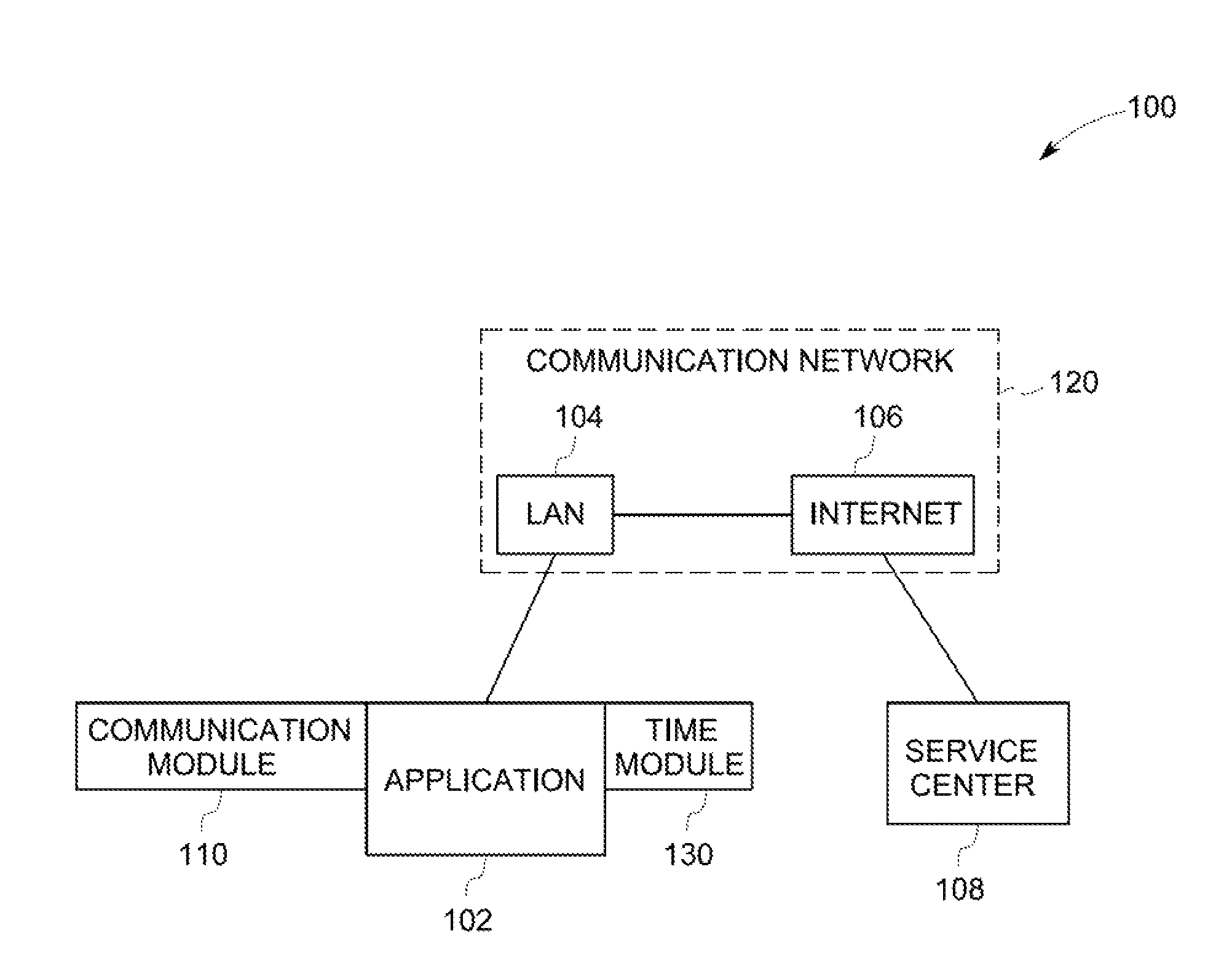
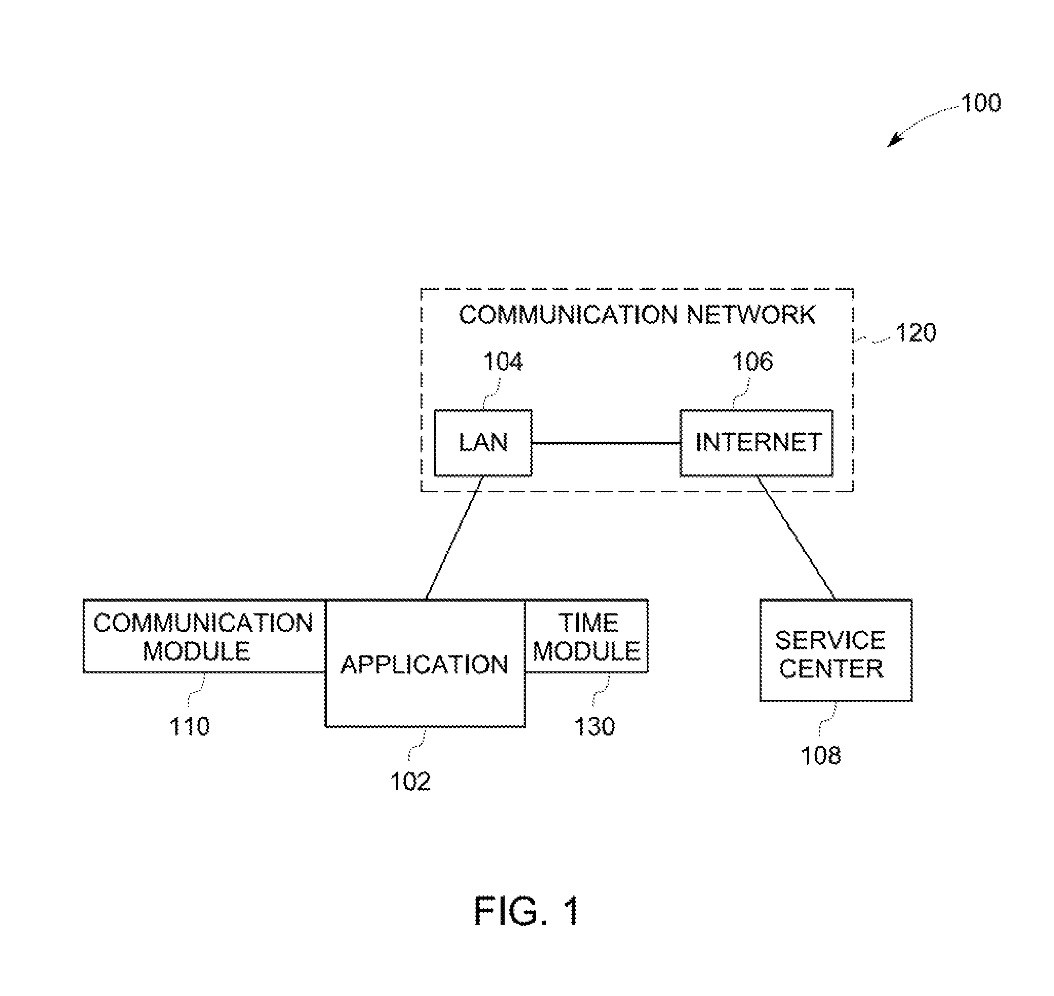
[0015]FIG. 1 illustrates a block diagram of a system incorporating aspects of the disclosed embodiments. As can be seen in FIG. 1, an appliance 102 is communicatively coupled to a service center 108 via a communication network 120. The appliance 102 is configured to transmit data in real-time corresponding to the operation and operational components (“operational data”) of the appliance 102 to the service center 108. The real-time operational data can be collected and analyzed at the service center 108 for, inter alia, failure analysis and diagnostics, appliance performance tracking, operational and diagnostic feedback, and generating alarms.

[0016]In one embodiment, the appliance 102 is communicatively coupled to a local area network (LAN) 104, such as for example, a wireless local area network (WLAN). The local area network 104 will typically be the users local or home network. The appliance 102 will generally be in communicative proximity to the local area network 104 to enable th...


PUM


Abstract

A method and system for monitoring an appliance is disclosed. The method includes establishing a wireless communication connection between a communication module in an appliance and a communication network, transmitting operational data in real-time from the appliance to an external monitoring system over the communication network, determining a status of a component of the appliance from the real-time operational data, and if a failure mode of the component is detected, initiating a service protocol corresponding to the component.

Description

BACKGROUND OF THE INVENTION[0001]The aspects of the disclosed embodiments generally relate to appliances. More particularly, the aspects of the disclosed embodiments relate to remotely monitoring appliance operational data in real-time.[0002]One example of a conventional remote maintenance system for an appliance is described in U.S. Pat. No. 6,772,096. This type of system generally includes a server located in the home (home server) and is connected to a service center server. The appliance includes a monitoring circuit that monitors an internal state of the appliance. The internal state is reported to the home server, which sends the information on to the center server. The center server holds a failure decision model for the appliance that determines a failure of the appliance.[0003]The home server can also hold a failure decision model corresponding to the appliance model. The home server can detect a failure of the appliance and notify the center server of the failure.[0004]How...

Claims


Application Information

Patent Timeline
Patent Type & Authority Patents(United States)
IPC IPC(8): G08B1/08
CPCH04L12/2825H04L12/2829H04L43/0817
Inventor WATSON, ERIC K.HAMEL, TIMOTHY A.DEVOS, RICHARDVENKATAKRISHNAN, NATARAJANDAWES, CHARLESKELLO, MICHAELGOTTIPATI, RAJENDRA PRASADGANIERE, DONALDROOT, STEVEN KEITH
Owner HAIER US APPLIANCE SOLUTIONS INC
Why Eureka
Try Eureka