
Communication control system, switch node and communication control method

a communication control system and switch node technology, applied in the field of communication control systems, can solve the problems of limited capacity of the transfer table connected with the hardware-based, low transfer processing ability of the switch node, and difficulty in configuring the switch nod

Inactive Publication Date: 2014-01-16
NEC CORP
View PDF6 Cites 32 Cited by
  • Summary
  • Abstract
  • Description
  • Claims
  • Application Information

AI Technical Summary

Benefits of technology

The patent describes a software-based switch node that can quickly switch between large amounts of data. This technology allows for high-speed processing and reduces latency.

Problems solved by technology

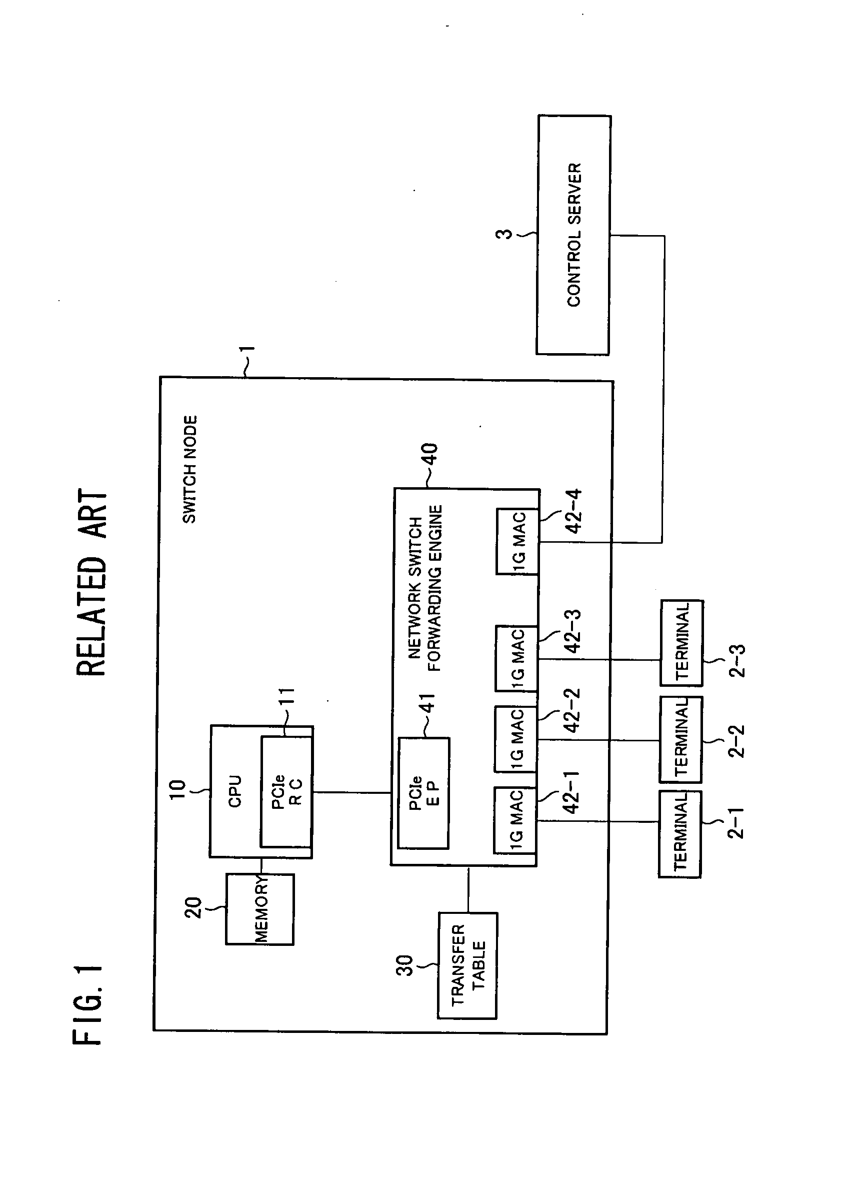
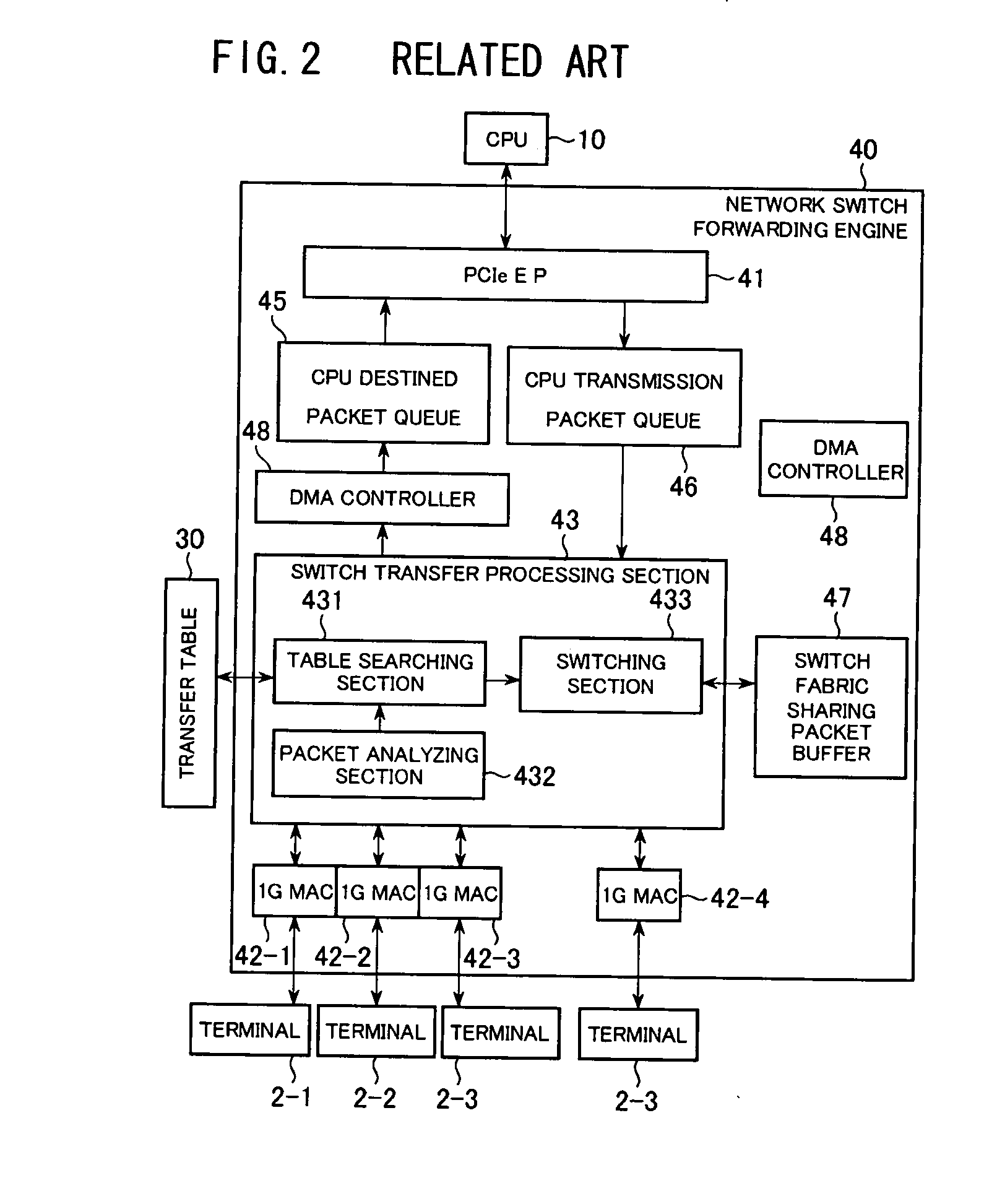
In a conventional switch node configuration, there is a limitation in the capacity of the transfer table connected with the hardware-based forwarding engine and it is difficult to configure the switch node which has a great deal of transfer tables.
On the other hand, when the software-based switch node is configured, there is a problem with low transfer processing ability in the switch node, because the CPU is one.

Method used


Image

  • Communication control system, switch node and communication control method
  • Communication control system, switch node and communication control method
  • Communication control system, switch node and communication control method

Examples


first exemplary embodiment

[First Exemplary Embodiment]

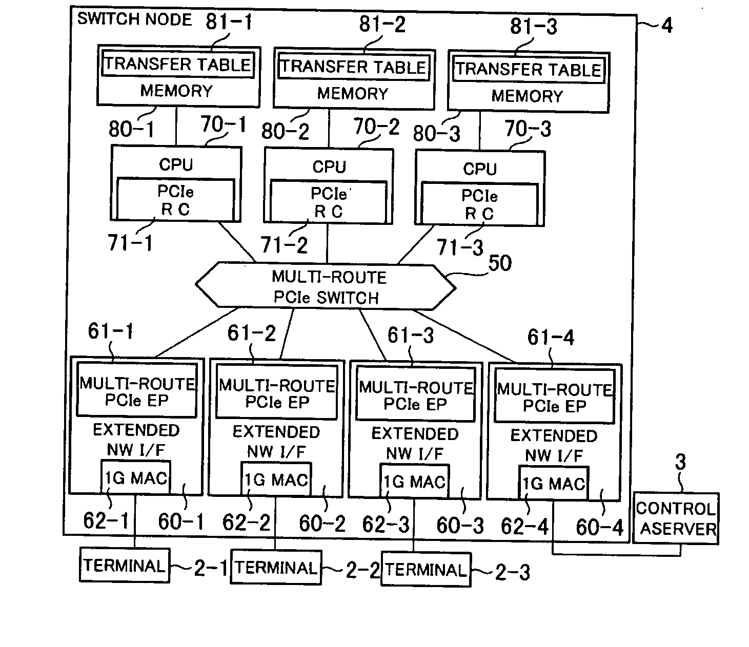
[0250]FIG. 14 shows a configuration example of the switch node according to a first exemplary embodiment.

[0251]The communication control system according to the present exemplary embodiment contains the terminals 2 (2-i, i=1 to T), the control server 3 and the switch node 5.

[0252]The terminals 2 (2-i, i=1 to T) and the control server 3 are the same as described previously.

[0253]The switch node 5 includes a LAN switch 100, a CPU and memory 110 (110-y, y=1 to N), a PCI express (PCIe) switch and network virtualizatian interface (NW virtualization I / F) 120 (120-y, y=1 to N), a single route PCI express endpoint (PCIe EP) and extended network interface (extended NW I / F) 130 (130-x, x=1 to (M+1)), and a multi-route PCI express (PCIe) switch and network virtualization interface (NW virtualization I / F) 140 (140-x, x=1 to (M+1)).

[0254]The LAN switch 100 is an Ethernet switch (Ethernet (registered trademark) switch), and connects the PCI express (PCIe) switch, the n...

second exemplary embodiment

[Second Exemplary Embodiment]

[0262]Also, FIG. 15 shows a configuration example of the switch node according to a second exemplary embodiment.

[0263]FIG. 15 is a configuration in which the CPU (70-y, y=1 to N) portion of FIG. 14 is changed into a GPU (Graphics Processing Unit) in which a great deal of processors are installed.

[0264]When using GPU, the packet processing may be carried out by the GPU instead of the CPU because the speeding-up of the packet processing can be expected and it is possible to connect to the PCI express (PCIe).

[0265]However, because the GPU is an I / O unit, one of the CPUs needs to be connected as a master CPU.

[0266]The communication control system according to the present exemplary embodiment contains the terminals 2 (2-i, i=1 to T), the control server 3 and the switch node 6.

[0267]The terminals 2 (2-i, i=1 to T) and the control server 3 are the same as described previously.

[0268]The switch node 6 includes the LAN switch 100, the CPU and memory 110, the PCI e...


PUM


Abstract

In a switch node connected with an external control server, a high functional service protocol processing can be realized by utilizing a multi-route compatible switch and a network interface (NW I / F), which are prescribed by the PCI express. Specifically, in a system which is provided with a switch node and a control server, a plurality of CPUs having a great deal of memories and a plurality of extended NW I / Fs are connected by a multi-route compatible PCI express switch, to configure a switch port of the plurality of extended NW I / Fs. Load distribution transfer processing to the plurality of CPUs from the network interfaces is made possible.High-speed packet processing is realized through the multiple processing by using the plurality of CPUs. A high-speed switch node is provided in which a large-capacity flow table is configured with the software-based switch node by using a large-capacity memory space of the CPU.

Description

TECHNICAL FIELD[0001]The present invention relates to a communication control system, and especially to a communication control system which controls a switch node.BACKGROUND ART[0002]A conventional network equipment is a black box and flexible control such as load distribution and bias processing cannot be carried out from outside. Therefore, when the scale of the network became large, there is a problem that the improvement and recognizing of conducts of a system become difficult and a design and change of the configuration requires a large cost.[0003]As a technique of solving such a problem, a technique of separating a packet transfer function and a route control function in a network equipment is thought of. For example, the network equipment takes charge of the packet transfer function and a control unit outside the network equipment takes charge of the route control function. Thus, the control becomes easy and a flexible network can be built.[0004](Explanation of CD separation...

Claims


Application Information

Patent Timeline
Patent Type & Authority Applications(United States)
IPC IPC(8): H04L12/933H04L45/42H04L49/111
CPCH04L49/15H04L12/00
Inventor HIDAKA, YOUICHI
Owner NEC CORP
Learn More