Method and system for providing a read transducer having an adaptive read sensor track width

a technology of read sensor and track width, which is applied in the field of providing a read transducer having an adaptive read sensor track width, can solve the problems that the conventional read transducer b>10/b> may not perform as desired

Active Publication Date: 2013-12-03
WESTERN DIGITAL TECH INC
View PDF14 Cites 153 Cited by
  • Summary
  • Abstract
  • Description
  • Claims
  • Application Information

AI Technical Summary

Benefits of technology

[0007]FIGS. 1A-1B depict ABS and plan views of a

Problems solved by technology

Without such changes, the conventional rea

Method used


Image

  • Method and system for providing a read transducer having an adaptive read sensor track width
  • Method and system for providing a read transducer having an adaptive read sensor track width
  • Method and system for providing a read transducer having an adaptive read sensor track width

Examples


Embodiment Construction

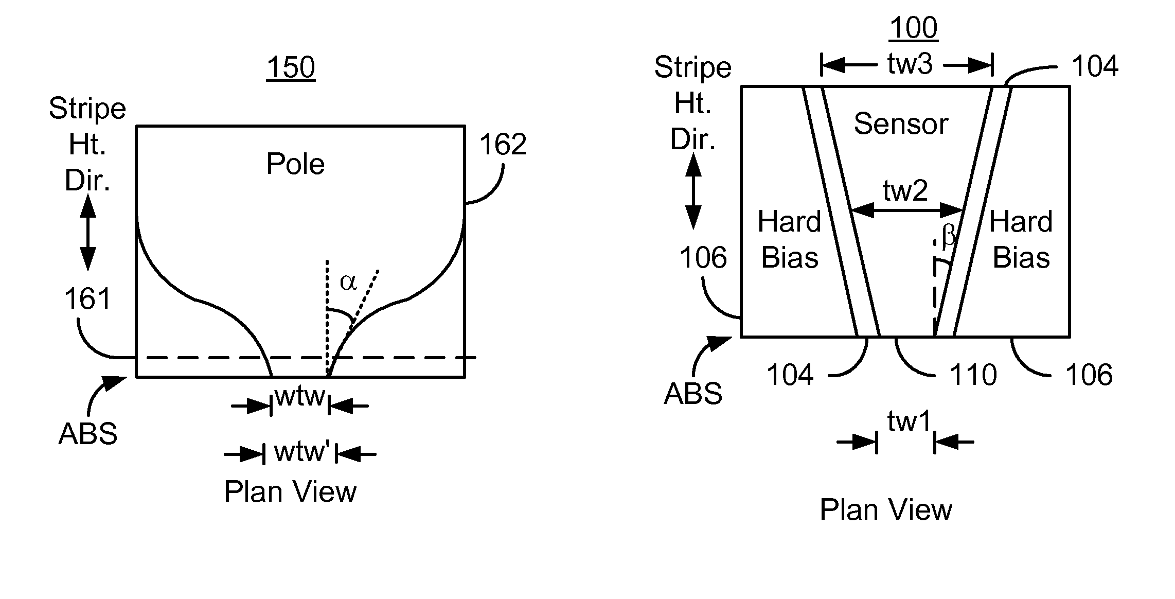
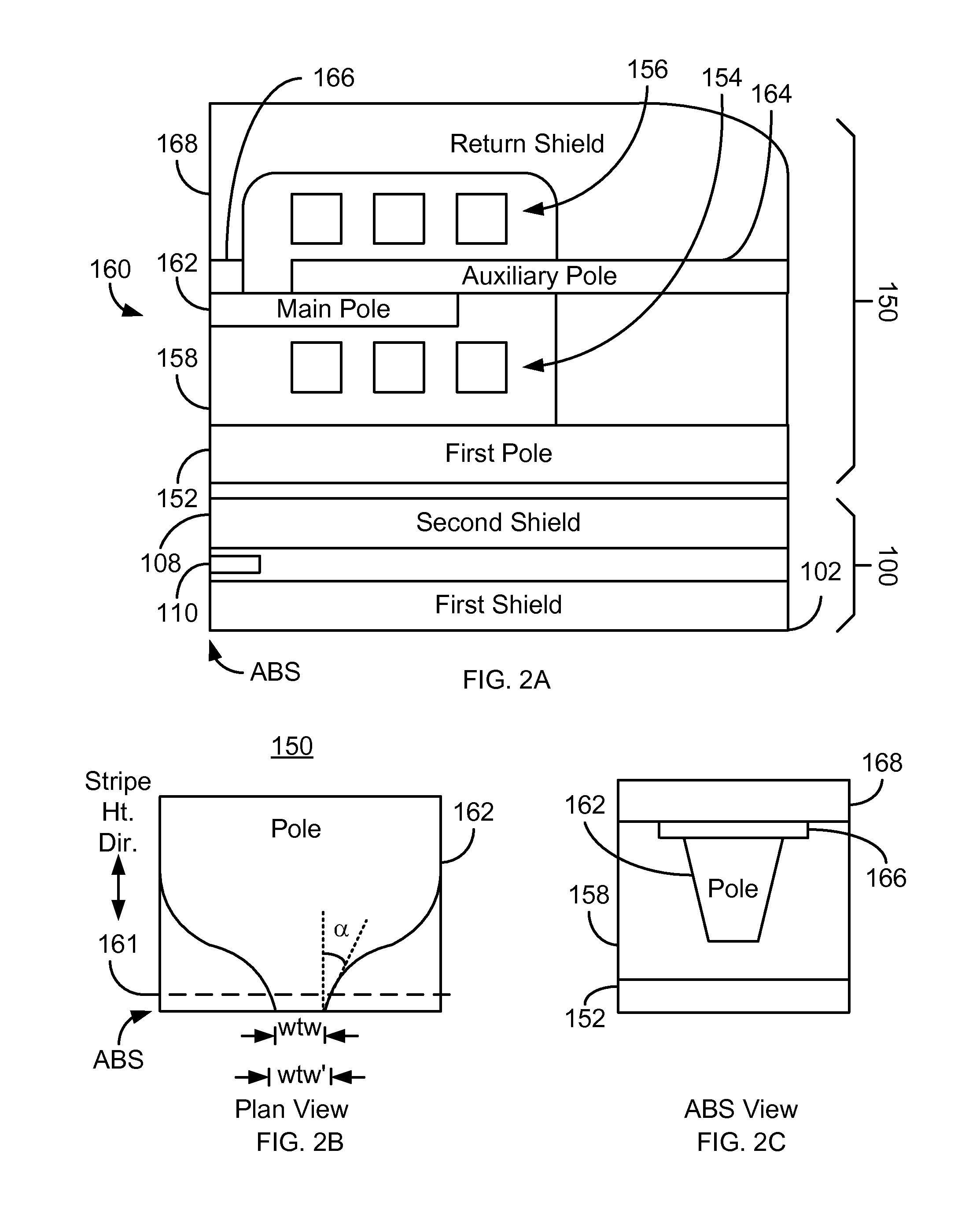
[0013]FIGS. 2A-2E depict various views of an exemplary embodiment of a portion of a magnetic read head. FIG. 2A depicts a side view of the head including a read transducer 100 and a write transducer 150. FIGS. 2B-2C depict plan and ABS views of the write transducer 150. FIGS. 2D-2E depict plan and ABS views of the read transducer 100. For clarity, FIGS. 2A-2E are not to scale. Although shown as part of a merged head, in other embodiments, the read transducer 100 may not be part of a stand-alone read head. The head of which the read transducer 100 and write transducer 150 are a part is part of a disk drive having a media, a slider and the head coupled with the slider. Further, only a portion of the components of the read transducer 100 and write transducer 150 are depicted.

[0014]The write transducer 150 includes poles 152 and 160, insulator 158, coils 154 and 156, return shield 158 and gap 166. The pole 160 includes a main pole 162 and an auxiliary pole 164. As can be seen in FIGS. 2...


PUM


Abstract

A method and system provide a magnetic read transducer having an air-bearing surface (ABS). The magnetic transducer includes a first shield, a second shield, and a read sensor between the first shield and the second shield. The read sensor extends along a stripe height direction perpendicular to the ABS. A first portion of the read sensor at the ABS has a first width in a track width direction parallel to the ABS. A second portion of the read sensor is recessed from the ABS along the stripe height direction and has a second width in the track width direction. The second width is greater than the first width.

Description

BACKGROUND[0001]FIGS. 1A-1B depicts an air-bearing surface (ABS) and plan views of a conventional read transducer used in magnetic recording technology applications. The conventional read transducer 10 includes shields 12 and 18, insulator 14, hard bias structures 16, and sensor 20. The read sensor 20 is typically a giant magnetoresistive (GMR) sensor or tunneling magnetoresistive (TMR) sensor.[0002]The read sensor 20 includes an antiferromagnetic (AFM) layer 22, a pinned layer 24, a nonmagnetic spacer layer 26, and a free layer 28. Also shown is a capping layer 30. In addition, seed layer(s) may be used. The free layer 28 has a magnetization sensitive to an external magnetic field. Thus, the free layer 28 functions as a sensor layer for the magnetoresistive sensor 20. If the sensor 20 is to be used in a current perpendicular to plane (CPP) configuration, then current is driven in a direction substantially perpendicular to the plane of the layers 22, 24, 26, and 28. Conversely, in a...

Claims


Application Information

Patent Timeline
IPC IPC(8): G11B5/127G11B5/39
CPCG01R33/09G11B5/3912G11B5/3932G11B5/398G01R33/093
Inventor LIU, FENGCHEN, LAURENCE L.GUO, YIMINRANA, AMRITPAL S.LI, SHAOPING
Owner WESTERN DIGITAL TECH INC
Why Eureka
Try Eureka