Composite antenna and portable telephone

a portable telephone and antenna technology, applied in the field of mobile phones, can solve the problems of reducing the chances of the user's hand coming to simultaneously cover both the main antenna and the auxiliary antenna, and deteriorating the reception conditions, and achieve the effect of greater miniaturization

Active Publication Date: 2013-12-03
KYOCERA CORP
View PDF14 Cites 11 Cited by
  • Summary
  • Abstract
  • Description
  • Claims
  • Application Information

AI Technical Summary

Benefits of technology

[0010]The complex antenna of the present invention allows for greater miniaturization. By implementing the complex antenna, the mobile phone of the present invention also allows further miniaturization to be realized.

Problems solved by technology

In contrast, the auxiliary antenna is used instead of the main antenna when, for example, the main antenna happens to be covered by the mobile phone user's hand supporting the mobile phone casing and thereby causing deterioration of the reception conditions.
This reduces the chances of the user's hand coming to simultaneously cover both the main antenna and the auxiliary antenna.

Method used


Image

  • Composite antenna and portable telephone
  • Composite antenna and portable telephone
  • Composite antenna and portable telephone

Examples


embodiment 1

[0019][Embodiment 1]

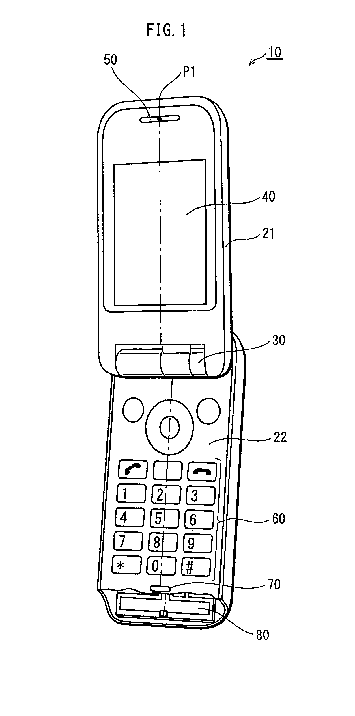
[0020]FIG. 1 is a perspective diagram of a mobile phone 10 pertaining to Embodiment 1 of the present invention. The mobile phone 10 is a clamshell phone made up of a first casing 21 and a second casing 22 connected via a hinge 30 so as to enable opening and closing. FIG. 1 illustrates a particular instance in which the first casing 21 and the second casing 22 are open. Ordinarily, when the mobile phone 10 is used for a call, the first casing 21 and the second casing 22 remain open, as shown in FIG. 1.

[0021]The first casing 21 includes a display unit 40 and an earphone unit 50, embedded therein. The display unit 40 is a liquid crystal display. As shown in FIG. 1, the screen of the display unit 40 is provided on the surface of the first casing 21 and is exposed when the first casing 21 and the second casing 22 are open. The earphone unit 50 includes a speaker. When the mobile phone 10 is used for a call, the speaker reproduces sounds produced by the other party in ...

embodiment 2

[0053][Embodiment 2]

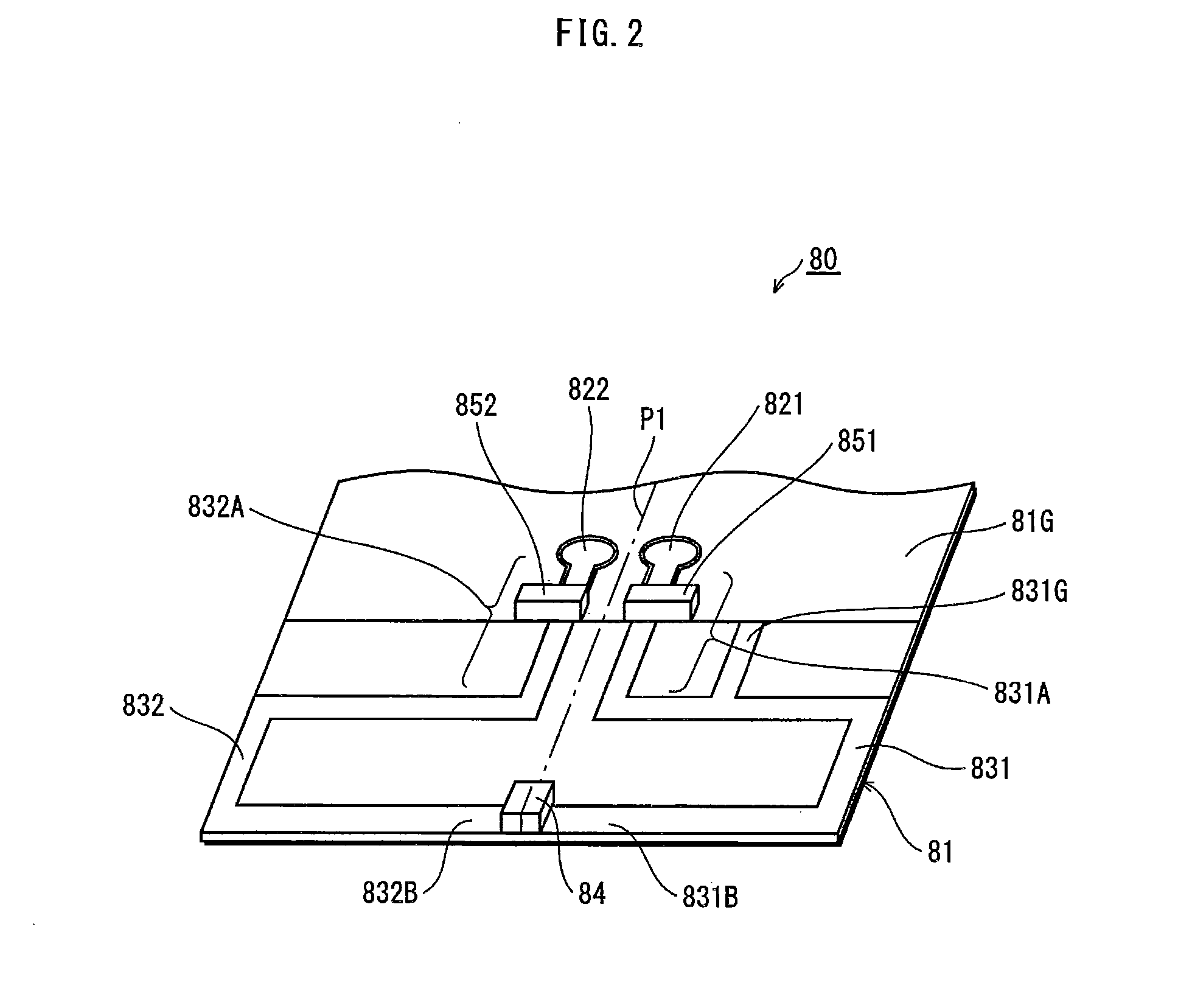
[0054]FIG. 5 is an equivalent circuit diagram of the complex antenna 80A pertaining to Embodiment 2 of the present invention. The complex antenna 80A differs from the complex antenna 80 shown in FIG. 3 in the inclusion of a series resonant circuit 84A. Aside from this point, the complex antenna 80A pertaining to Embodiment 2 is identical to the above-described complex antenna 80 pertaining to Embodiment 1. That is, the complex antenna 80A shown in FIG. 5 is, like the complex antenna 80 shown in FIG. 2, disposed within the second casing 22 of the mobile phone 10 from FIG. 1, being particularly concentrated in the vicinity of the mouthpiece unit 70. Furthermore, the structure of the complex antenna 80A shown in FIG. 5 as implemented on the substrate is identical to that of the complex antenna 80 shown in FIG. 2. Accordingly, FIG. 5 uses the same reference numbers as FIGS. 1, 2, and 3 to refer to components identical to those of the complex antenna 80 pertaining to ...

embodiment 3

[0060][Embodiment 3]

[0061]FIG. 6 is a perspective diagram of a complex antenna 80B pertaining to Embodiment 3 of the present invention. FIG. 7 is an equivalent circuit diagram of the complex antenna 80B. The complex antenna 80B has a second antenna element 832 that differs from that of the complex antenna 80 shown in FIGS. 2 and 3. Aside from this point, the complex antenna 80B pertaining to Embodiment 3 is identical to the above-described complex antenna 80 pertaining to Embodiment 1. That is, the complex antenna 80B shown in FIG. 6 is, like the complex antenna 80 shown in FIG. 2, disposed within the second casing 22 of the mobile phone 10 from FIG. 1 and particularly concentrated in the vicinity of the mouthpiece unit 70. Furthermore, the complex antenna 80B shown in FIG. 6 includes elements identical to the complex antenna 80 shown in FIG. 2. Accordingly, FIGS. 6 and 7 use the same reference numbers as FIGS. 1, 2, and 3 to refer to components identical to those of the complex ant...


PUM


Abstract

A complex antenna has a first antenna element and a second antenna element each connected at one end to a different feed point and connected to each other at the other end through a parallel resonant circuit. Each antenna element has the same resonant frequency as the parallel resonant circuit. A mobile phone has an antenna switch with a first port connected to the first antenna element, a second port connected to the second antenna element, and a third port that can be connected to one of the first port and the second port and switched therebetween. A signal processing unit causes the antenna switch to connect the third port to the first port or to the second port and detects a signal captured by one of the antenna elements from the output of the third port.

Description

TECHNICAL FIELD[0001]The present invention relates to a mobile phone, and particularly relates to an antenna implemented therein.BACKGROUND ART[0002]A mobile phone often incorporates an auxiliary antenna in addition to a main antenna. Normally, the main antenna is used for communications. In contrast, the auxiliary antenna is used instead of the main antenna when, for example, the main antenna happens to be covered by the mobile phone user's hand supporting the mobile phone casing and thereby causing deterioration of the reception conditions. Thus, good communication conditions are maintained for the mobile phone. As such, the mobile phone is able to select one antenna from a plurality of antennas for use in communications, switching to another antenna whenever reception conditions deteriorate. This is termed a diversity function.[0003]In a conventional mobile phone, the main antenna and the auxiliary antenna are disposed within the casing at positions as far apart as possible. This...

Claims


Application Information

Patent Timeline
Patent Type & Authority Patents(United States)
IPC IPC(8): H04M1/00H01Q5/10
CPCH01Q21/28H01Q21/29H01Q1/243H01Q1/36H01Q9/0421
Inventor KATO, HISATOMO
Owner KYOCERA CORP
Why Eureka
Try Eureka