Moveable contact closing energy transfer system for miniature circuit breakers

a technology of energy transfer system and circuit breaker, which is applied in the field of circuit breakers, can solve the problems of reducing the useful life of circuit breakers, increasing costs, and expensive solutions, and achieves the effects of reducing wear and tear, relatively inexpensive energy transfer system, and negatively affecting electrical connections

Active Publication Date: 2013-12-10
SCHNEIDER ELECTRIC USA INC
View PDF13 Cites 4 Cited by
  • Summary
  • Abstract
  • Description
  • Claims
  • Application Information

AI Technical Summary

Benefits of technology

[0004]An energy transfer system of the present disclosure absorbs impact forces in a circuit breaker to reduce wear and tear on metal electrical contacts therein. The energy transfer system does so without significantly, negatively affecting the electrical connection between the contacts. The energy transfer system is relatively inexpensive as it only includes a rotatable member and a biasing member that can be retrofitted in a plurality of existing miniature circuit breakers with minimal modifications to the housings of the circuit breakers.

Problems solved by technology

The bouncing is undesirable because it can result in momentary arcing between the contacts that damage the contacts overtime and can reduce the useful life of the circuit breaker.
Prior attempts to account for the bouncing include providing more durable and hefty contacts; however, this is an expensive solution because the contacts are typically made of expensive materials (e.g., silver).
Other attempts to account for the bouncing involve complex mechanical arrangements that involve many additional moving components within a housing of the circuit breaker that increase costs and require a larger housing for the circuit breaker.

Method used


Image

  • Moveable contact closing energy transfer system for miniature circuit breakers
  • Moveable contact closing energy transfer system for miniature circuit breakers
  • Moveable contact closing energy transfer system for miniature circuit breakers

Examples


Embodiment Construction

[0028]Although the present disclosure will be described in connection with certain preferred embodiments, it will be understood that the present disclosure is not limited to those particular embodiments. On the contrary, the present disclosure is intended to include all alternatives, modifications and equivalent arrangements as may be included within the spirit and scope of the present disclosure as defined by the appended claims.

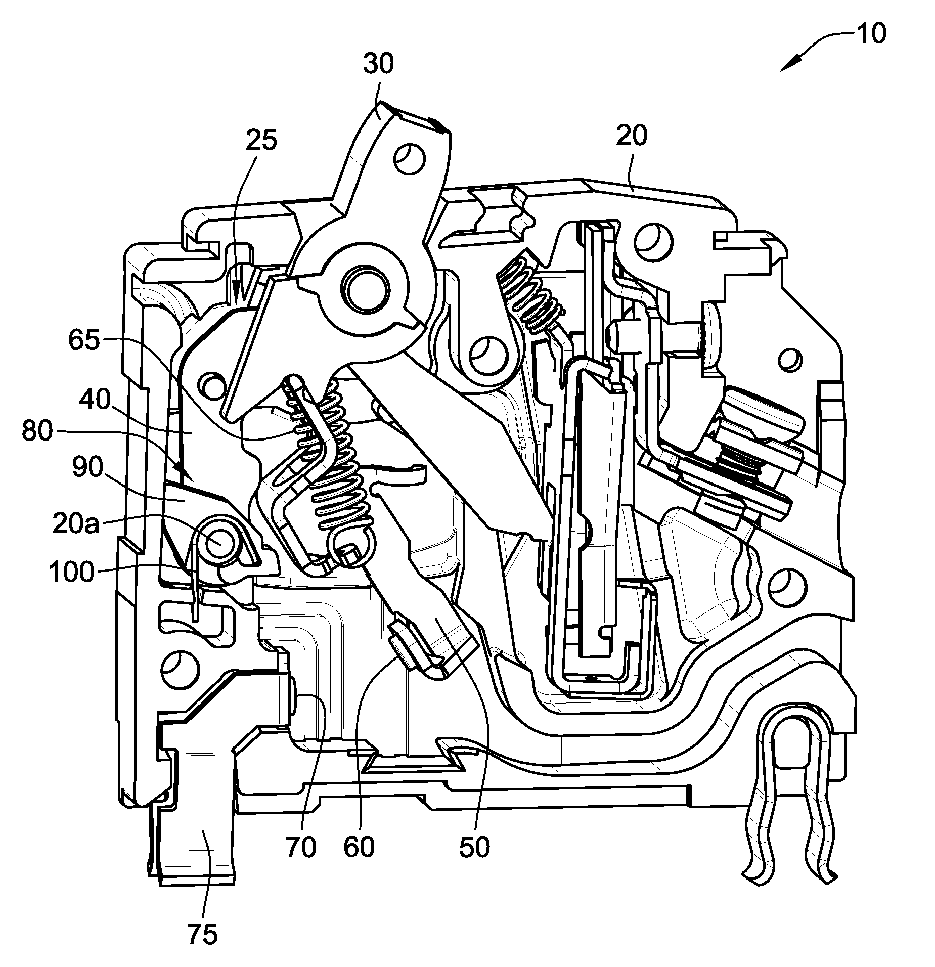
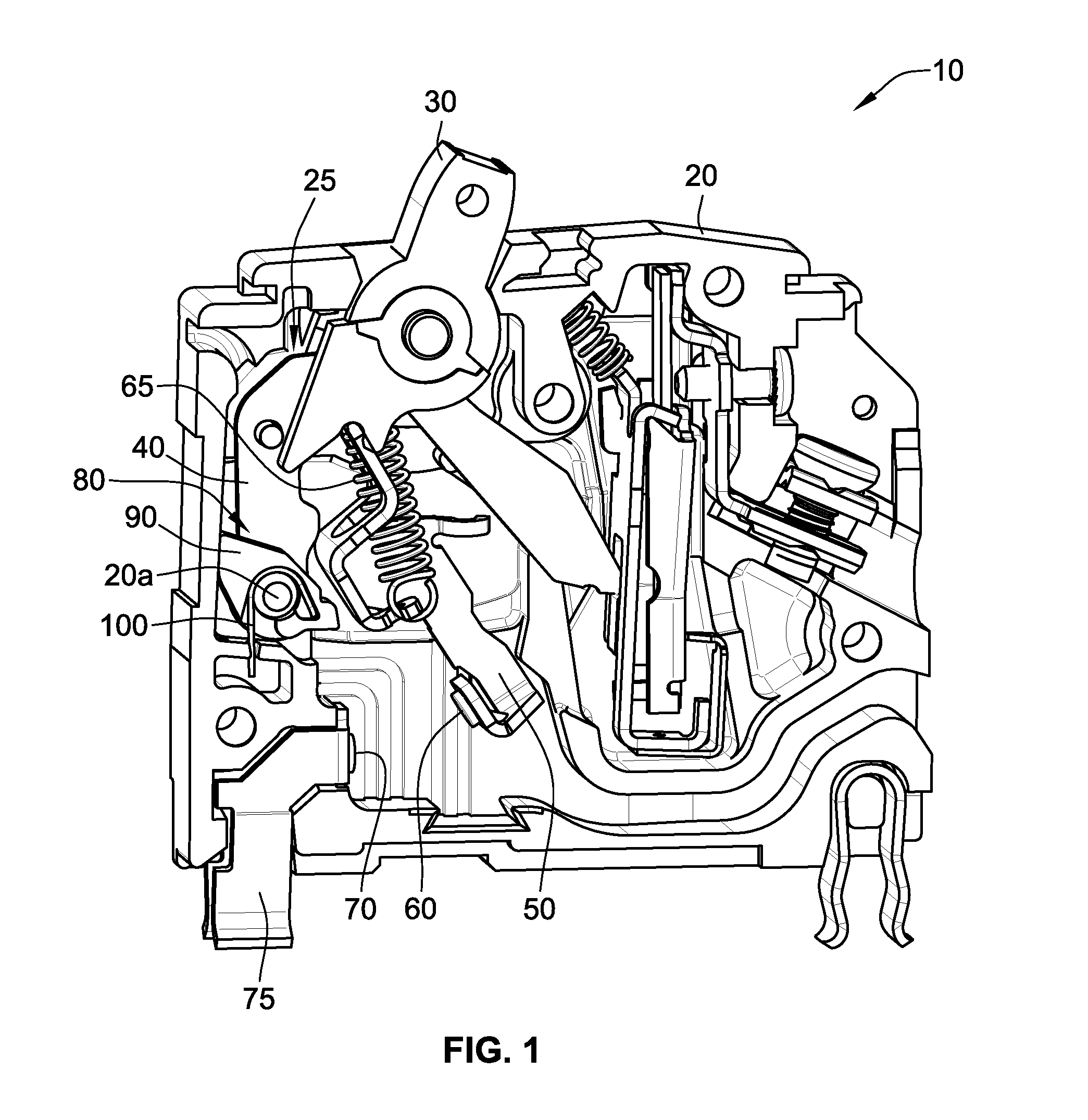
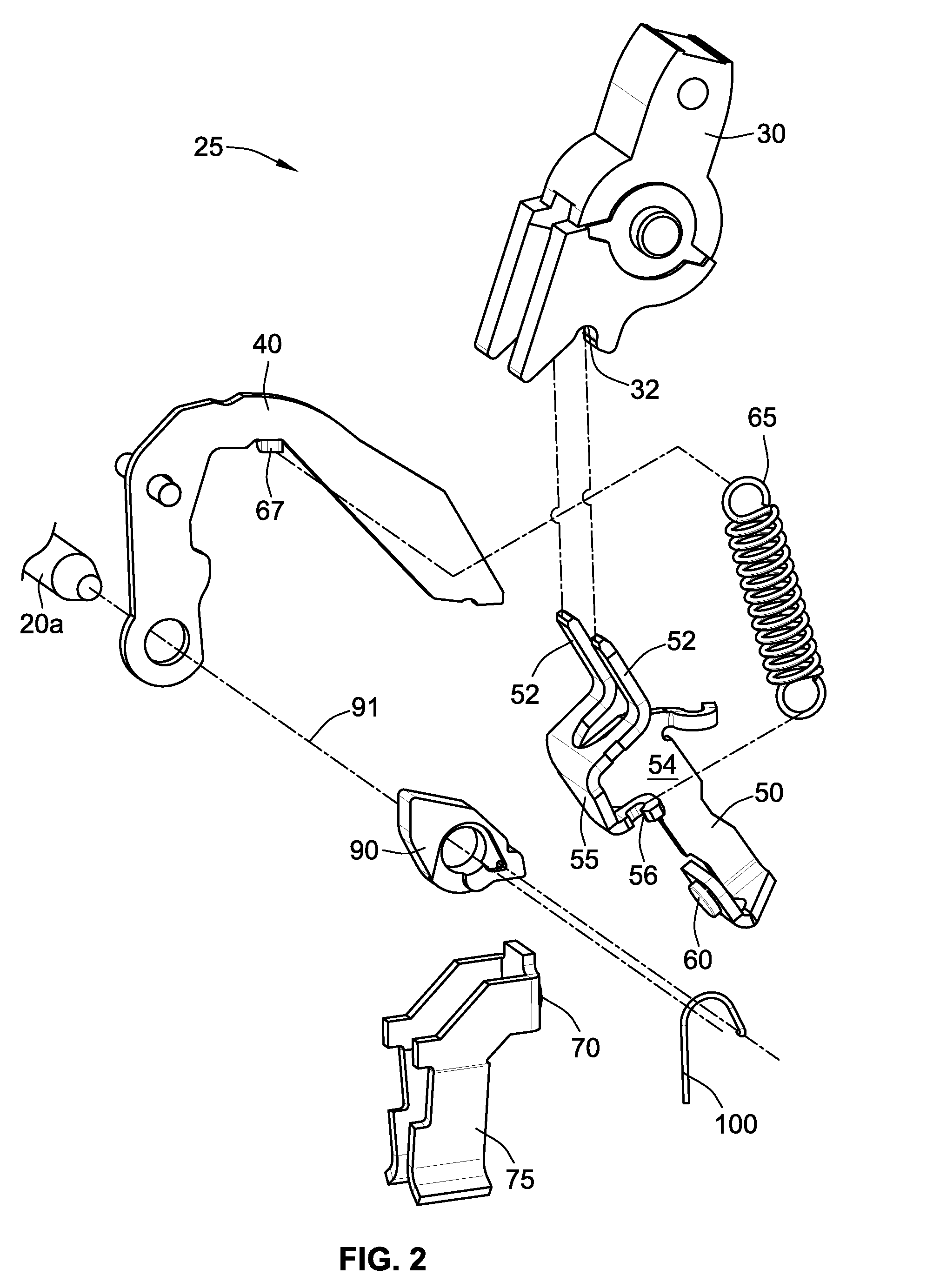
[0029]Referring to FIG. 1, a circuit breaker 10 with a cover removed (i.e., not shown) to illustrate internal components includes a housing 20, a switch assembly 25, and an energy transfer system 80. The switch assembly 25 and the energy transfer system 80 are both generally contained within the housing, except for a portion of the switch assembly 25 (e.g., an upper portion of a handle 30). Some components (e.g., bimetal, yoke, armature, terminals, etc.) of the circuit breaker 10 are omitted or not described, however, these components, which may be found in...


PUM


Abstract

An energy transfer system absorbs impact forces and / or energy from a moveable conductive blade directly attached to a moveable contact in a circuit breaker. The energy transfer system includes a rotatable member and a biasing member. The rotatable member has an axis of rotation about which the rotatable member is rotatable between a first position and a second position. The rotatable member further includes a protrusion. The protrusion has an initial curved engagement surface portion, a planar engagement surface portion next to the initial curved engagement surface portion, and a final curved engagement surface portion next to the planar engagement surface portion. The biasing member biases the rotatable member towards the first position. The movable conductive blade impacts the initial curved engagement surface portion to cause the rotatable member to begin to rotate about the axis of rotation such that the moveable conductive blade then contacts the planar engagement surface portion and then the final curved engagement surface portion.

Description

FIELD OF THE INVENTION[0001]This invention is directed generally to a circuit breaker, and, more particularly, to a circuit breaker having an energy transfer system.BACKGROUND OF THE INVENTION[0002]Circuit breakers provide automatic and manual current interruption to a circuit. The act of turning ON a circuit breaker and closing an electrical circuit typically involves a mechanical movement of a series of mechanical parts that results in a moveable contact making an electrical connection with a stationary contact. The mechanical movement can result in the moveable contact engaging the stationary contact with a significant impact force and energy such that the moveable contact bounces on the stationary contact prior to coming to rest thereon. The bouncing is undesirable because it can result in momentary arcing between the contacts that damage the contacts overtime and can reduce the useful life of the circuit breaker. Prior attempts to account for the bouncing include providing more...

Claims


Application Information

Patent Timeline
Patent Type & Authority Patents(United States)
IPC IPC(8): H01H23/00
CPCH01H1/50H01H71/504H01H71/524
Inventor MITTELSTADT, CHAD R.
Owner SCHNEIDER ELECTRIC USA INC
Why Eureka
Try Eureka