
Quick release hand guard assembly for a rifle

a hand guard and rifle technology, applied in the field of rifle rifle gunstocks, can solve the problems of affecting the accuracy of weapons, affecting the flight path of projectiles, and the slight shift of the barrel alignmen

Inactive Publication Date: 2013-12-17
ZINSNER BRENDON B
View PDF19 Cites 77 Cited by
  • Summary
  • Abstract
  • Description
  • Claims
  • Application Information

AI Technical Summary

Benefits of technology

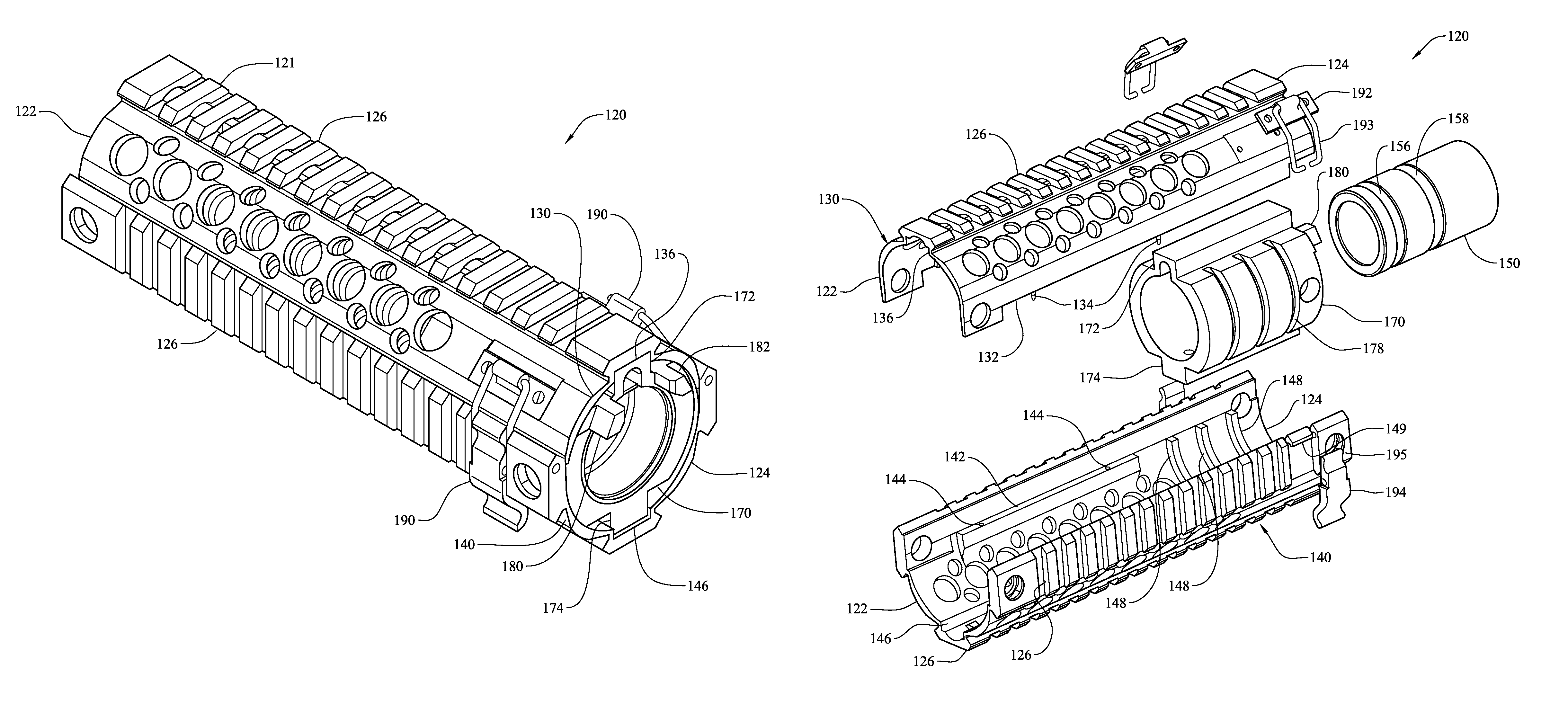
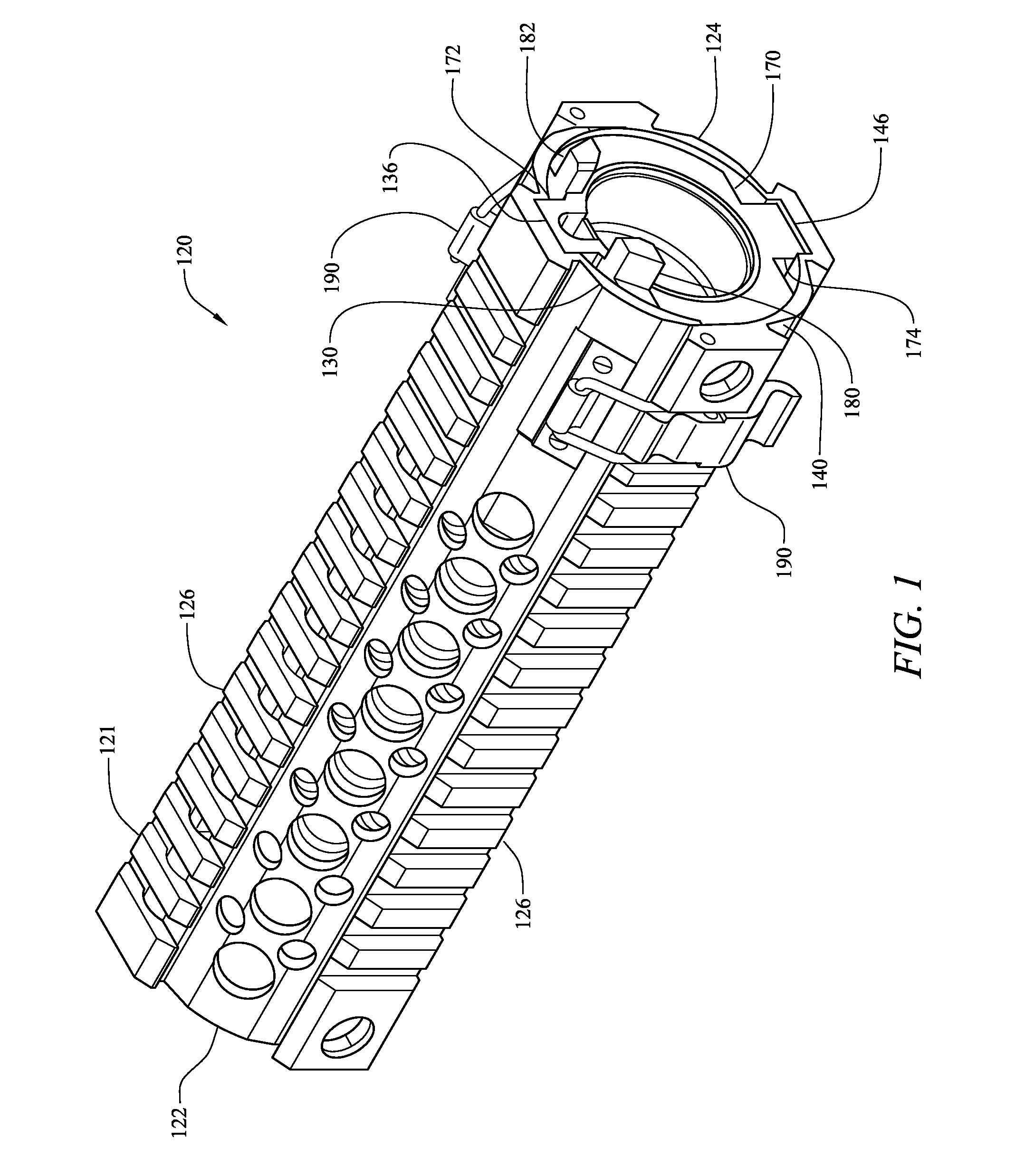
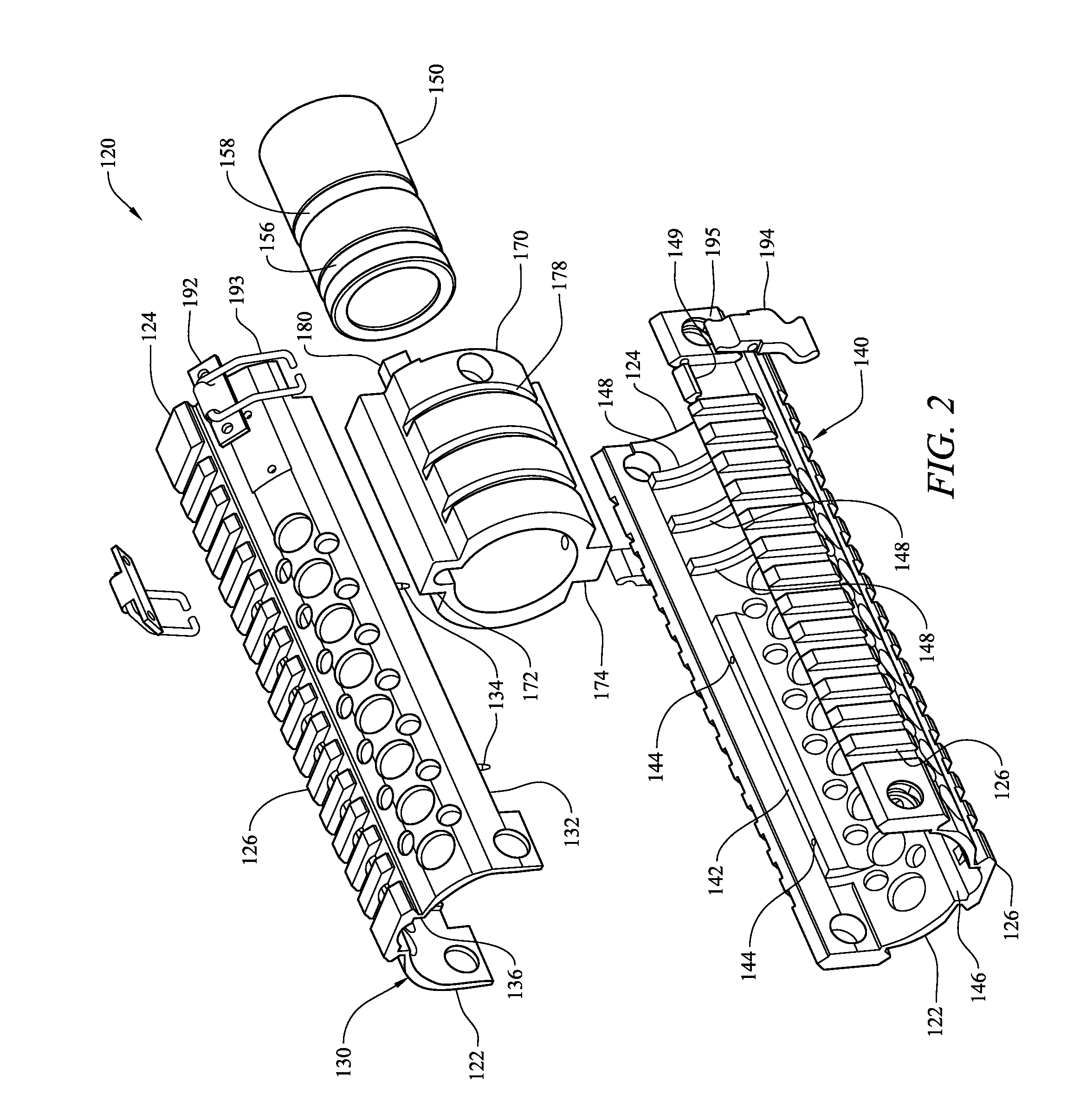
The present invention is about a hand guard assembly for a rifle. It consists of an inner nut and an outer barrel nut that are secured together and a first and second hand guard element that surround the barrel. The hand guard elements are attached to each other with a quick release fastener. The hand guard assembly is free floating, meaning it is not attached to the barrel or the receiver of the rifle. The technical effect of this invention is a quick and easy way to install a hand guard assembly on a rifle that provides stability and protection without interfering with the use of the firearm.

Problems solved by technology

If the stock is manufactured of wood, environmental conditions or operational use may shift the alignment of the stock, which, in turn, may cause the barrel to shift its alignment slightly over time.
This shift can alter the flight path of the projectile and thus its impact point.
Contact between the barrel and the stock also interferes with the natural frequency of the barrel, which, in some cases, can be detrimental on the weapon's accuracy.
The interference of the stock with the barrel's forced oscillation as the projectile passes down the bore can cause the barrel to vibrate inconsistently from shot to shot, depending on the external forces acting upon the stock at the time of the shot.
Micro-vibrations acting during the projectile's passage result in differences in trajectory as the projectile exits the bore, thus changing the downrange impact point.

Method used


Image

  • Quick release hand guard assembly for a rifle
  • Quick release hand guard assembly for a rifle
  • Quick release hand guard assembly for a rifle

Examples


Embodiment Construction

[0022]The following detailed description is merely exemplary in nature and is not intended to limit the described embodiments or the application and uses of the described embodiments. As used herein, the word “exemplary” or “illustrative” means “serving as an example, instance, or illustration.” Any implementation described herein as “exemplary” or “illustrative” is not necessarily to be construed as preferred or advantageous over other implementations. All of the implementations described below are exemplary implementations provided to enable persons skilled in the art to make or use the embodiments of the disclosure and are not intended to limit the scope of the disclosure, which is defined by the claims. For purposes of description herein, the terms “upper”, “lower”, “left”, “rear”, “right”, “front”, “vertical”, “horizontal”, and derivatives thereof shall relate to the invention as oriented in FIG. 1. Furthermore, there is no intention to be bound by any expressed or implied theo...


PUM


Abstract

A quick release, free floating, multi-piece forward hand guard assembly for a rifle includes an inner barrel nut adapted to be affixed to a front of the rifle receiver and an outer barrel nut telescopically received over the inner barrel nut and longitudinally secured thereto. The outer barrel nut is non-rotatable with respect to the inner barrel nut. A first hand guard element is engaged with and extends forwardly from the outer barrel nut in a laterally stable cantilevered fashion, and a second hand guard element is matingly engaged with the first hand guard element for surrounding the rifle's barrel and is free floating therefrom. The second hand guard element is attached to the first hand guard element with at least one quick release fastener.

Description

FIELD OF THE INVENTION[0001]The present disclosure generally relates to gunstocks for rifles. More particularly, the present disclosure relates to a two-piece cantilevered forward shield for an automatic rifle.BACKGROUND OF THE INVENTION[0002]Gunstocks for handheld weapons date back to the sixteenth century and are derived from the Germanic word ‘stoc’, meaning tree trunk, referring to the wooden nature of the gunstock. Those early ‘hand cannons’ used a simple stick fitted into a socket in the breech end of the weapon to provide a handle for the user. Over the following centuries, gunstocks typically remained fashioned from wood, although the shape of the gunstock evolved to the gunstock of the twentieth century that is most recognizable with a butt stock for placing against a shooter's shoulder including a grip and a fore end or hand guard. Initially, gunstocks were one piece from butt to fore end, but certain weapon configurations lent themselves to two-piece stocks where the fore...

Claims


Application Information

Patent Timeline
Patent Type & Authority Patents(United States)
IPC IPC(8): F41C23/16
CPCF41C23/16
Inventor ZINSNER, BRENDON B
Owner ZINSNER BRENDON B
Learn More