Fuel injector having a high-pressure inlet

a fuel injector and high-pressure technology, applied in the direction of combustion types, machines/engines, lighting and heating apparatus, etc., can solve the problems of high production effort and expense, stress in the region, etc., and achieve the effect of reducing stress in this region and optimal utilization of materials

Active Publication Date: 2013-12-17
ROBERT BOSCH GMBH
View PDF9 Cites 5 Cited by
  • Summary
  • Abstract
  • Description
  • Claims
  • Application Information

AI Technical Summary

Benefits of technology

[0008]It is therefore the object of the present invention to create a fuel injector in which intersections between the inlet bore and the valve chamber are embodied in such a way that stresses in this region are reduced, while at the same time optimal utilization of material prevails.
[0009]The invention includes the technical teaching that the inlet bore, beginning at the pressure connection, along its length has a fanlike contour with a defined fan angle and a variable cross section of oblong-slotlike form. By this provision, an increased pressure area is generated in the axial direction, which leads to a stress reduction in the vicinity of the intersection of the inlet bore and the valve chamber. Thus a shift in the maximum stress can be attained, out of the region of the intersecting lines into the axial vicinity of the inlet bore, and as a result the machining effort and expense in the vicinity of the intersections can be reduced. Moreover, by the fanlike design of the inlet bore, optimal utilization of material is achieved.
[0011]In a further advantageous feature of the invention, the fanlike contour is formed by at least two bores, and the center axes of the respective outer bores, beginning at a connecting axis of the pressure connection and valve chamber each extend by half the fan angle, pivoted in the direction of the valve chamber. By this provision, the fanlike contour of the inlet bore can be created at a low production cost, because in the simplest case two bores are placed, which to form the fanning out of the inlet are pivoted accordingly by half the fan angle relative to the connecting axis located between the valve chamber and the pressure connection.
[0013]In a further advantageous feature of the invention, the respective outer bores of the fanlike contour of the inlet bore, with their center axes, are not located outside a respective angle, equal to a tangent, of a cross section of the valve chamber. It is advantageous in this respect that the outer regions of the inlet bore are not located too far outside the valve chamber, and thus no overly great deflection of the flowing fuel in the direction of the valve chamber is required.
[0014]In a refinement of the invention, the fanlike contour of the inlet bore, on its end toward the valve chamber, has a rounded end with the form of a concavely curved annular portion. As a result, the inflow of fuel to the valve chamber at the end of the inlet bore is improved further.

Problems solved by technology

A disadvantage of the known prior art is that with the present systems, the production effort and expense are high, and the incident stresses in the region of the intersections can be reduced further by improving their geometry.

Method used


Image

  • Fuel injector having a high-pressure inlet
  • Fuel injector having a high-pressure inlet
  • Fuel injector having a high-pressure inlet

Examples


Embodiment Construction

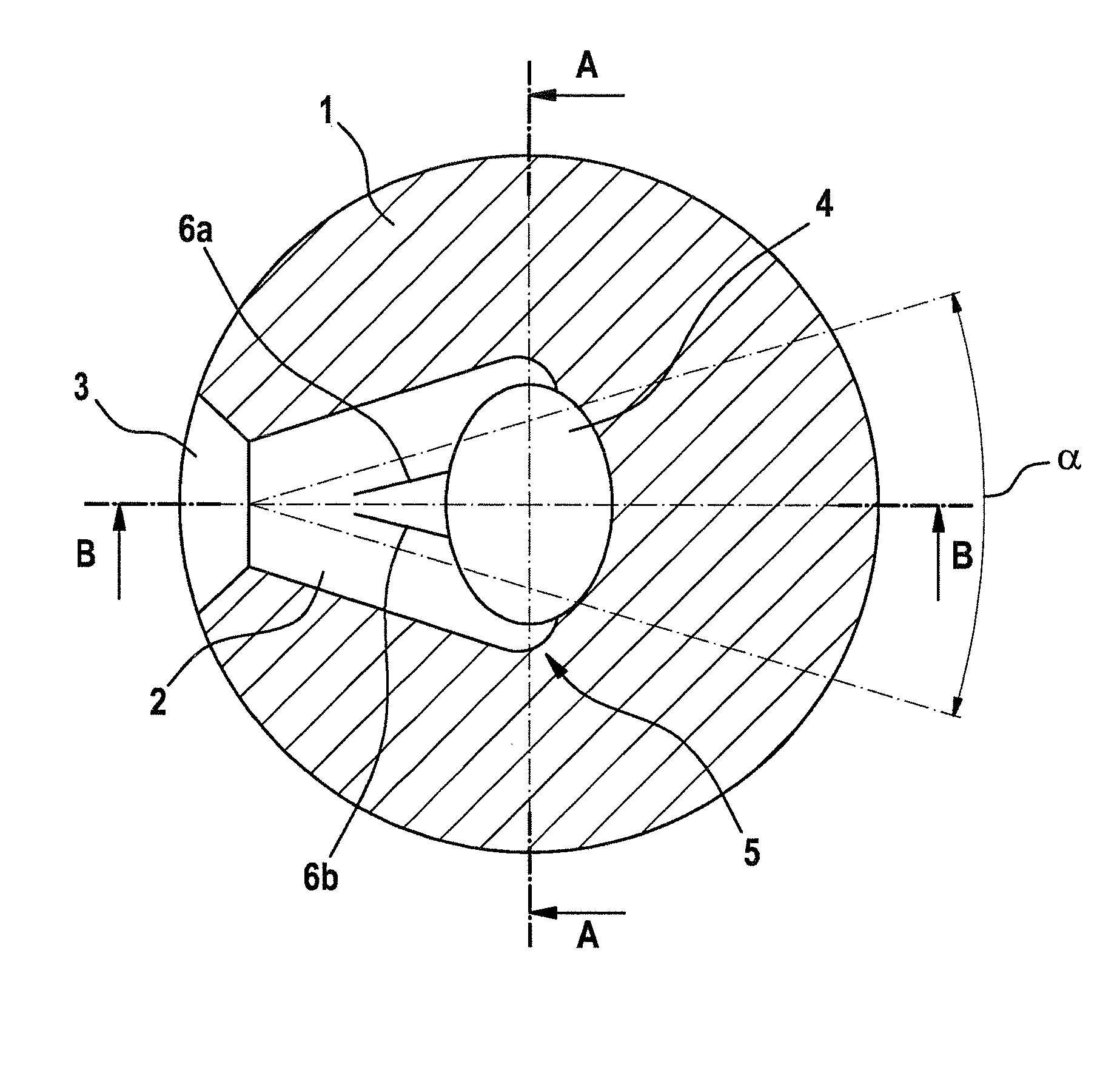
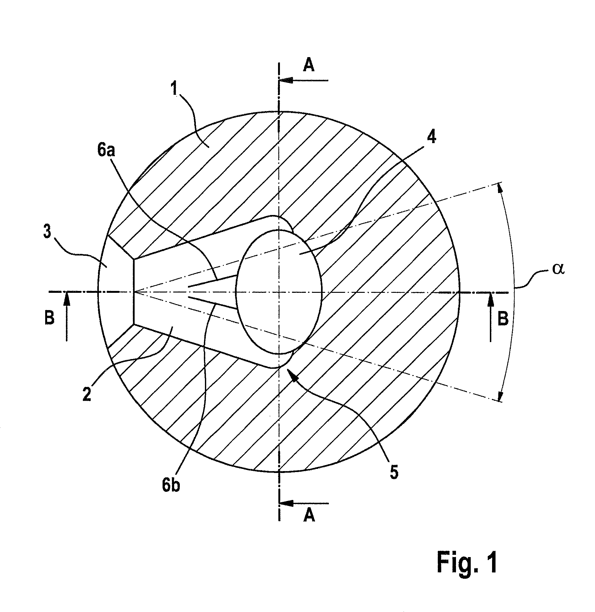
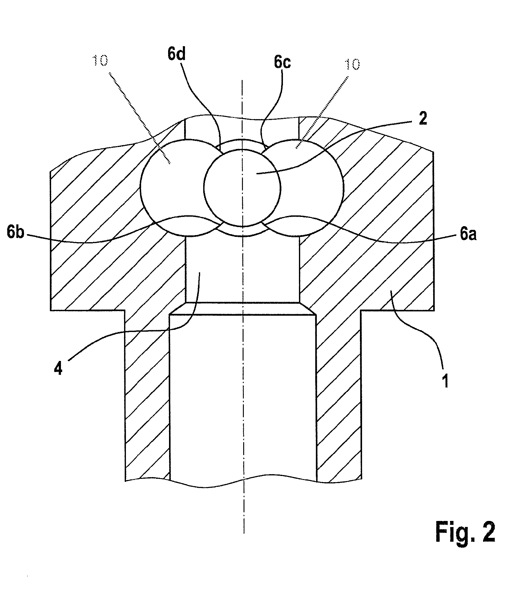
[0023]In FIG. 1, a sectional view of the fuel injector of the invention can be seen; the section has been placed perpendicular to a longitudinal center axis of the injector body 1. In this sectional view, an inlet bore 2 connects a conical pressure connection 3 with a valve chamber 4. As can be seen from FIG. 1, the valve chamber 4 is embodied elliptically. To create an increased pressure area in the axial direction of the inlet bore 2, the pressure area is embodied in fanlike fashion and, beginning at the conical pressure connection 3, extends at the angle α in the direction of the valve chamber 4. In the embodiment shown, an inlet bore 2 of this kind is created by making three individual bores in the injector body 1. The first bore is extended, beginning at the conical pressure connection 3, rectilinearly in the direction of the longitudinal center axis of the injector body 1. The two outer bores 10 are created, again beginning at the pressure connection 3, by drilling in pivoted ...


PUM


Abstract

The invention relates to a fuel injector for the operation of an internal combustion engine, having an injector body. An inlet bore of the injector body connects a conical pressure connection to a valve chamber for supplying highly pressurized fuel. The valve chamber is placed along a longitudinal center axis of the injector body and above a nozzle needle. According to the invention, the inlet bore further has a fan-shaped contour starting at the conical pressure connection along the extension thereof, the contour having a fan angle and a variable cross-section in the shape similar to an elongated hole.

Description

CROSS-REFERENCE TO RELATED APPLICATION[0001]This application is a 35 USC 371 application of PCT / EP 2009 / 055891 filed on May 15, 2009.BACKGROUND OF THE INVENTION[0002]1. Field of the Invention[0003]The invention relates to a fuel injector for the operation of an internal combustion engine, having an injector body in which an inlet bore connects a conical pressure connection with a valve chamber for delivering fuel that is at high pressure, and the valve chamber is placed along a longitudinal center axis of the injector body and above a nozzle needle.[0004]2. Description of the Prior Art[0005]From German Patent Disclosure DE 101 52 230 A1, a fuel injector is already known in the injector body of which a valve chamber is in communication with a pressure connection via an inlet bore. In the region of the intersections between the valve chamber and the inlet bore, bellied portions of the cross section are also provided, in order to reduce the notch stresses in this region and thus overal...

Claims


Application Information

Patent Timeline
Patent Type & Authority Patents(United States)
IPC IPC(8): B05B1/30F02M61/00F02M63/00F02M39/00F02M41/00
CPCF02M55/005F02M55/008F02M55/02F02M61/16
Inventor GIRLINGER, GERHARDHABERLOVA, MARCELAEBERHART, ARTHUR
Owner ROBERT BOSCH GMBH
Why Eureka
Try Eureka