

Optical fiber panel and preparation method thereof
A technology of optical fiber panel and plate segment, which is applied in the direction of bundled optical fiber, etc., to achieve the effects of improving material utilization rate, correcting magnification distortion, and improving material utilization rate
- Summary
- Abstract
- Description
- Claims
- Application Information
AI Technical Summary
Problems solved by technology
Method used
Image

Examples
preparation example Construction
[0026] An embodiment of the present invention proposes a method for preparing an optical fiber panel, which includes:
[0027] The secondary multifilament is obtained by pulling the monofilament, arranging the multifilament rod once, pulling the multifilament once, arranging the multifilament rod twice, and pulling the multifilament twice; the diameter of the second multifilament is 0.5-5mm;
[0028] Cutting the secondary multifilament to obtain the first multifilament and the second multifilament;
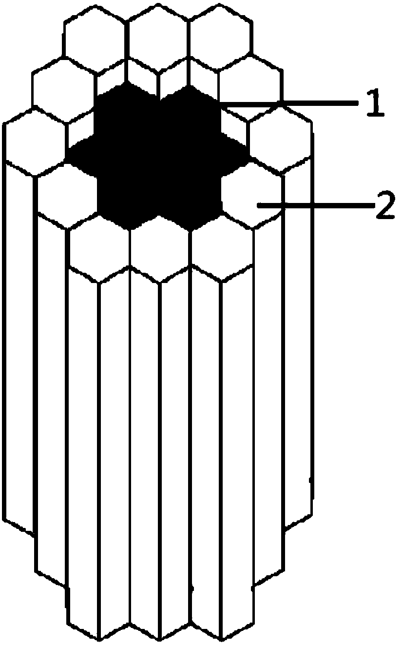
[0029] closely packing the first multifilament into a hexagonal prism shape to obtain a first plate segment;
[0030] Wrapping the second multifilament on the first plate segment to obtain the second plate segment;
[0031] Melting, pressing and machining the second plate section to obtain an optical fiber panel;
[0032] Wherein, the length of the second multifilament is greater than the length of the first multifilament, and the length difference between the second multifilame...
Embodiment 1
[0039] An embodiment of the present invention proposes a method for preparing an optical fiber panel, which includes:
[0040] The secondary multifilament is obtained by pulling the monofilament, arranging the multifilament rod once, pulling the multifilament once, arranging the multifilament rod twice, and pulling the multifilament twice; the diameter of the second multifilament is 1mm;
[0041] The secondary multifilament is cut to obtain the first multifilament and the second multifilament; wherein the length of the first multifilament is 120 mm, and the length of the second multifilament is 130 mm.
[0042] Arranging the first multifilaments into a regular hexagonal prism in a closely packed manner to obtain a first plate segment; wherein the number of first multifilaments on one side of the regular hexagonal prism is 16;
[0043] Wrapping the second multifilaments on the first plate section to obtain the second plate section; wherein the number of second multifilaments on...
Embodiment 2
[0050] An embodiment of the present invention proposes a method for preparing an optical fiber panel, which includes:
[0051] The secondary multifilament is obtained by drawing the monofilament, arranging the multifilament rod once, pulling the multifilament once, arranging the multifilament rod twice, and drawing the multifilament twice; the diameter of the second multifilament is 0.5mm;
[0052] The secondary multifilament is cut to obtain the first multifilament and the second multifilament; wherein the length of the first multifilament is 50 mm, and the length of the second multifilament is 55 mm.
[0053] Arranging the first multifilaments in a closely packed manner into a regular hexagonal prism to obtain a first plate segment; wherein the number of first multifilaments on one side of the regular hexagonal prism is 8;
[0054] Wrapping the second multifilament on the first plate segment to obtain the second plate segment; wherein the number of second multifilaments on o...
PUM
| Property | Measurement | Unit |
|---|---|---|
| Wire diameter | aaaaa | aaaaa |
| Wire diameter | aaaaa | aaaaa |
| Length | aaaaa | aaaaa |
Abstract
Description
Claims
Application Information