Camera module

a technology of camera module and module body, which is applied in the field of camera module, to achieve the effect of reducing the risk of oscillation of a servo system and reducing the vibration of elastic members

Active Publication Date: 2013-12-17
SHARP KK
View PDF16 Cites 31 Cited by
  • Summary
  • Abstract
  • Description
  • Claims
  • Application Information

AI Technical Summary

Benefits of technology

[0017]A camera module in accordance with the present invention is a camera module having a function of compensating for hand shake, including: a moving part including image capturing lenses; a driving means for moving the moving part in a direction perpendicular to a direction of an optical axis of the image capturing lenses; suspension wires, which extend parallel to or at an angle to the direction of the optical axis, for supporting the moving part such that the moving part is moved in the direction perpendicular to the optical axis; elastic members, connected to at least one ends of the respective suspension wires, each suppressing stress to be applied to a corresponding one of the suspension wires; and damper members, applied to the respective elastic members, which cause a reduction in vibrations of the elastic members. Therefore, it is possible to reduce the risk of the oscillation of a servo system while ensuring drop-impact resistance.

Problems solved by technology

Although a system for compensating for hand shake has been widely used for digital cameras and camcorders, there have been only a few mobile phones equipped with systems for compensating for hand shake, due to the issue of a limited size of mobile phone.

Method used


Image

  • Camera module
  • Camera module
  • Camera module

Examples


embodiment 1

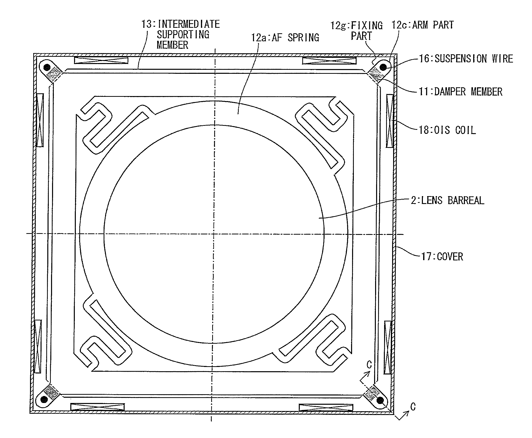
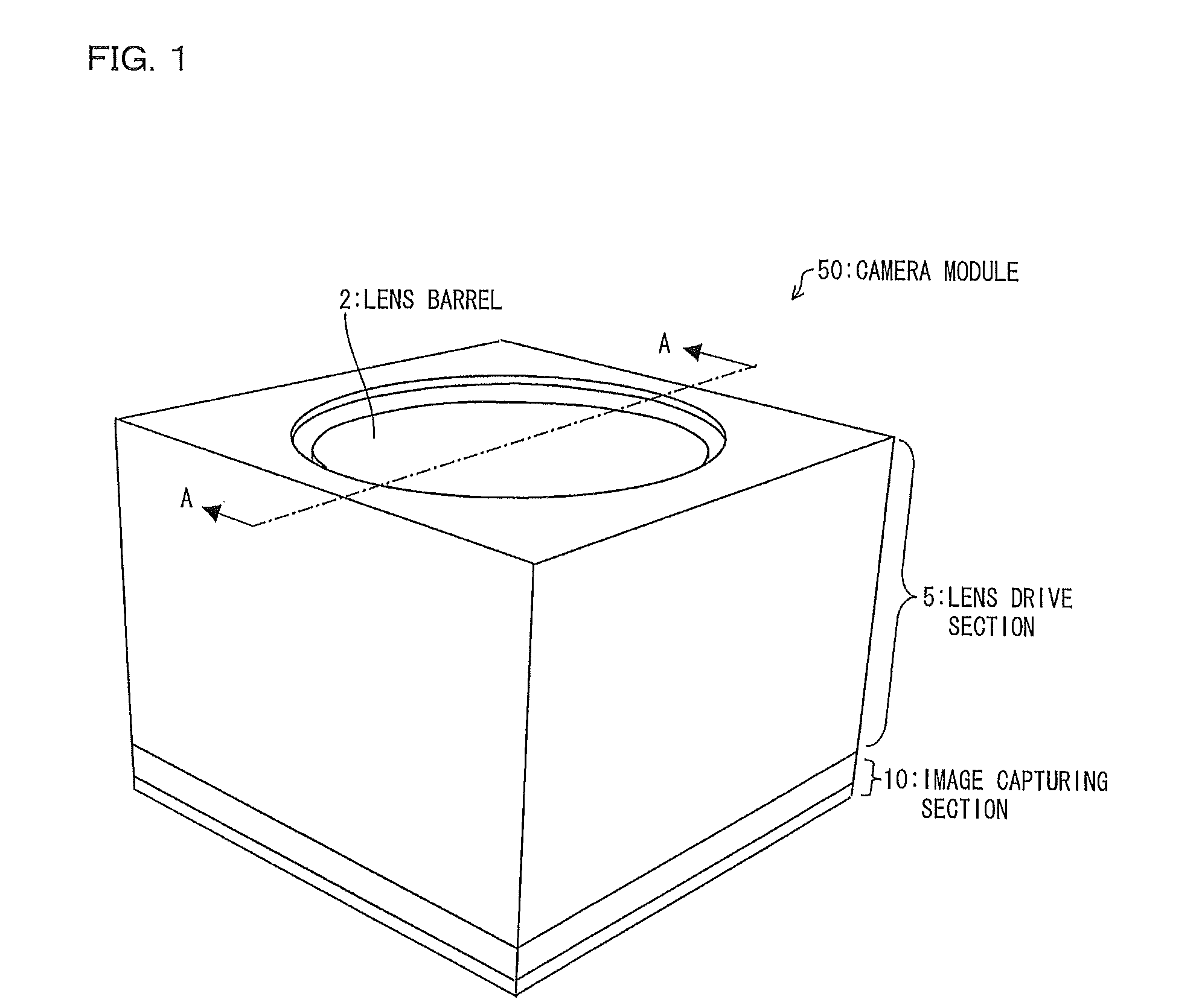
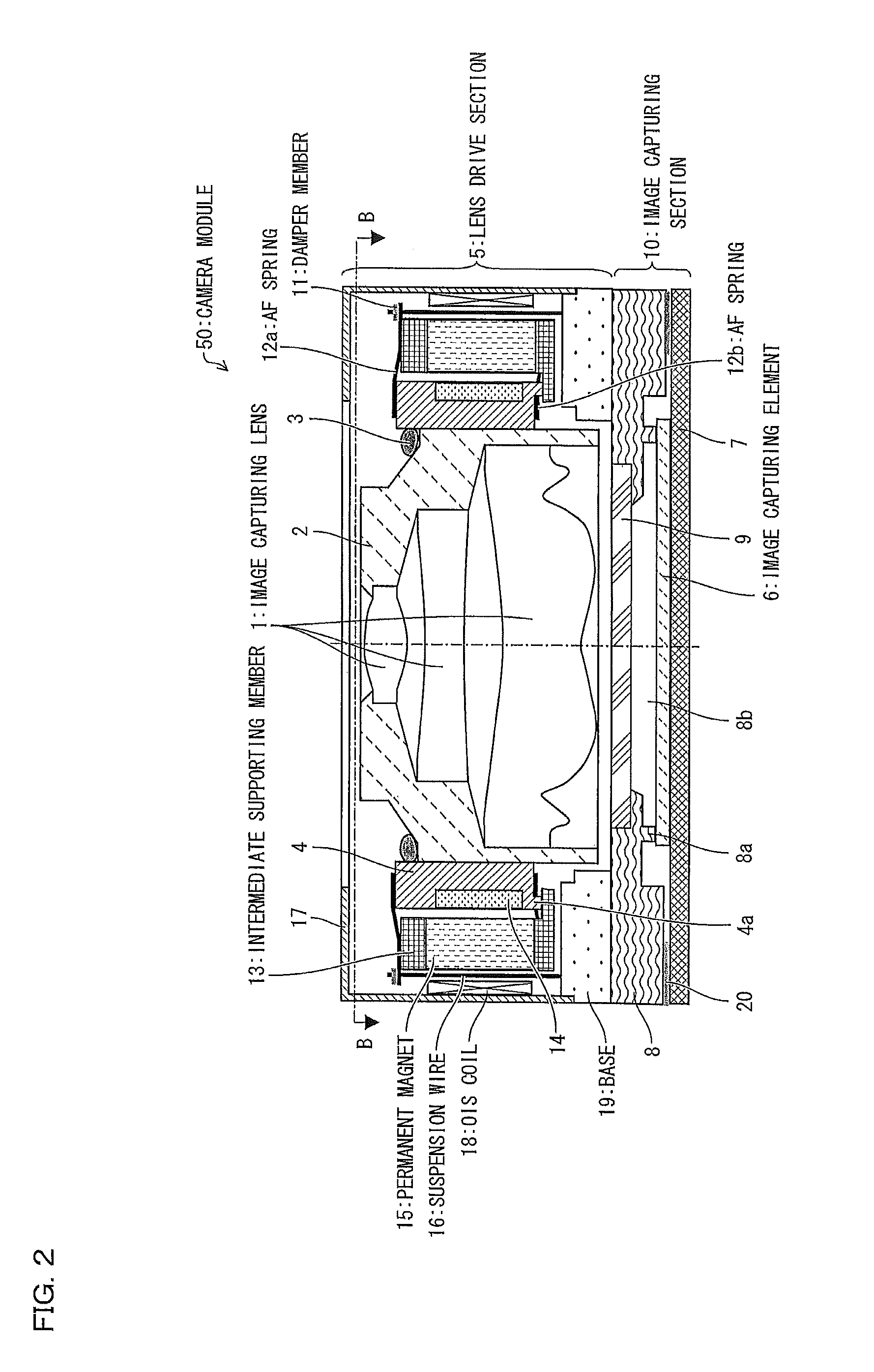
[0034]FIG. 1 is a perspective view schematically illustrating a configuration of a camera module 50 in accordance with Embodiment 1 of the present invention. FIG. 2 is a cross-sectional view taken along the line A-A of the camera module 50 illustrated in FIG. 1. FIG. 3 is a cross-sectional view taken along the line B-B of the camera module 50 illustrated in FIG. 2.

[0035](Camera Module)

[0036]As illustrated in FIGS. 1 through 3, the camera module 50 includes (i) image capturing lenses 1, (ii) a lens barrel 2 accommodating the image capturing lenses 1, and (iii) a lens holder 4 fixing the lens barrel 2 in the camera module 50 with the use of an adhesive 3.

[0037]The camera module 50 further includes (i) a lens drive section 5 for moving the image capturing lenses 1 in a direction of an optical axis of the image capturing lenses 1 (hereinafter, referred to as the optical-axis direction) and in directions of two axes each perpendicular to the optical-axis direction and (ii) an image captu...

embodiment 2

[0080]According to Embodiment 1, an arm part 12c, via which a suspension wire 16 and an OIS moving part are connected, functions as an elastic member for suppressing stress to be applied to the suspension wire 16. The present invention is, however, not limited to such. For example, it is possible to cause a connecting part, via which a suspension wire 16 and an OIS fixed part are connected, to function as an elastic member for suppressing stress to be applied to the suspension wire 16. The following description will discuss such a configuration as Embodiment 2 of the present invention.

[0081]FIG. 10 is a cross-sectional view schematically illustrating a configuration of a camera module 50 in accordance with Embodiment 2. FIG. 11 is an enlarged view illustrating a configuration, in the camera module 50, of an area around one of connecting parts of a suspension wire 16 and an OIS fixed part. Note that, in Embodiment 2, members whose functions are the same as those of Embodiment 1 are g...

embodiment 3

[0087]The following description will discuss how to better provide a damper member 11, while contrasting between an example configuration A illustrated in (a) of FIG. 12 and an example configuration B illustrated in (b) of FIG. 12. Both of (a) and (b) of FIG. 12 are cross-sectional views each taken along the line C-C drawn in FIG. 3. Hereinafter, (i) a part of a suspension wire 16, which part is connected to an arm part 12c, is referred to as a moving-part-side fixed end or as a first connecting part 16a, (ii) a part of the suspension wire 16, which part is connected to a base 19 is referred to as a fixed-part-side fixed end or as a second connecting part 16b, and (iii) a part of the suspension wire 16 between the first connecting part 16a and the second connecting part 16b is referred to as a flexible part 16c. The flexible part 16c bends in response to a movement of an OIS moving part.

[0088]In both the example configurations A and B, the suspension wire 16 (i) goes through an open...


PUM


Abstract

A camera module (50) having a function of compensating for hand shake includes: suspension wires (16) for supporting an intermediate supporting member (13); AF springs (12a) for refraining stress to be applied to the suspension wires (16); and damper members (11) for causing a reduction in vibrations of the AF springs (12a).

Description

[0001]This Nonprovisional application claims priority under 35 U.S.C. §119 on Patent Application No. 2011-177216, No. 2012-008482, and No. 2012-111953, filed in Japan on Aug. 12, 2011, Jan. 18, 2012, and May 15, 2012, respectively, the entire contents of which are hereby incorporated by reference.TECHNICAL FIELD[0002]The present invention relates to a camera module to be mounted on an electronic device such as a mobile phone, and, especially, to a camera module including a system for compensating for hand shake.BACKGROUND ART[0003]On the recent mobile phone market, types of mobile phones having built-in camera modules have been dominant. These camera modules are meant to be embedded in the mobile phones. Therefore, they face greater demands for being compact and lightweight, compared with camera modules to be embedded in digital cameras.[0004]Also, there have been an increasing number of camera modules that (i) operate their autofocus (AF) systems with the use of lens drive devices ...

Claims


Application Information

Patent Timeline
Patent Type & Authority Patents(United States)
IPC IPC(8): G03B17/00H04N5/228G02B27/64
CPCG03B17/00H04N5/2257H04N5/2328G03B5/02G03B17/12G03B2205/0015H04N23/57H04N23/685
Inventor SEKIMOTO, YOSHIHIRO
Owner SHARP KK
Why Eureka
Try Eureka