Frac light 3000

a technology of frac light and balloon, which is applied in the direction of semiconductor devices for light sources, lighting and heating apparatus, and support devices for lighting, etc. it can solve the problems of increasing costs, not providing any protection, and balloons not maximizing the efficiency of lighting sources

Inactive Publication Date: 2013-12-24
A&P SUPPORT
View PDF1 Cites 4 Cited by
  • Summary
  • Abstract
  • Description
  • Claims
  • Application Information

AI Technical Summary

Benefits of technology

[0009]The present invention solves the aforementioned deficiencies. The first improvement over prior-art illumination balloons is the frame. The frame of the present invention is preferably constructed of aluminum with a minimum of three vertical pillars that are hollow to allow electrical wiring to be threaded through the frame. The lighting sources of the present invention are staggered along the vertical pillars of the frame so each lighting source may emit its own light unimpeded from the fixtures and bulbs of the other lighting sources. The inflating means of the present invention comprises a 110 V fan assembly that does not require a transformer to step down the voltage originating from the main power source. The present invention is further comprised of known components, including a translucent membrane that is supported by the frame and inflated by the inflating means. When the lighting sources are energized and the membrane inflated, the present invention produces 360° of light.

Problems solved by technology

However, there are several known deficiencies associated with illumination balloons presently known in the art.
Known balloons are comprised of frames that are inherently weak and do not provide any protection for the electrical wiring that is typically routed around the frame.
Second, known balloons do not maximize the efficiency of the lighting source due to the physical location of each individual lighting source relative to each other.
Third, known balloons use an unnecessarily complicated means of energizing the inflating means of the balloon which increases costs and increases the risk of component failure.

Method used


Image

  • Frac light 3000
  • Frac light 3000
  • Frac light 3000

Examples


Embodiment Construction

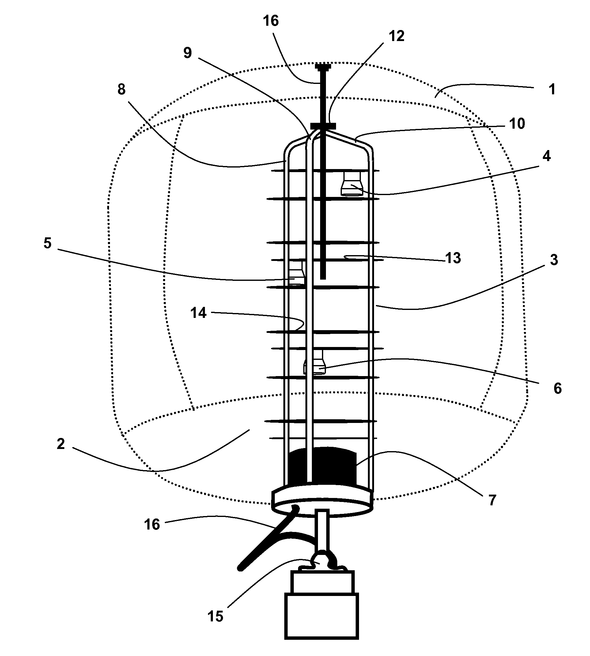
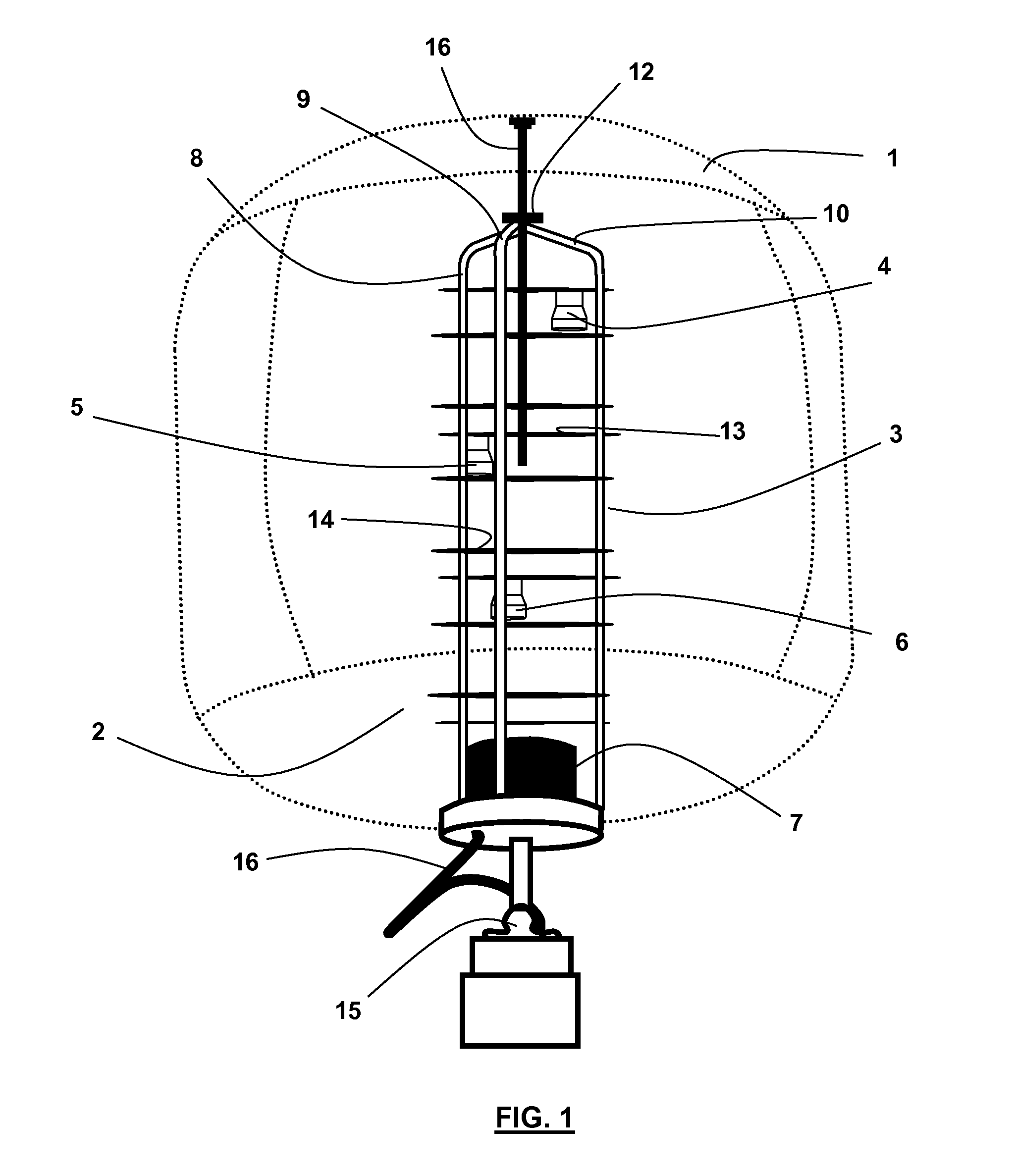
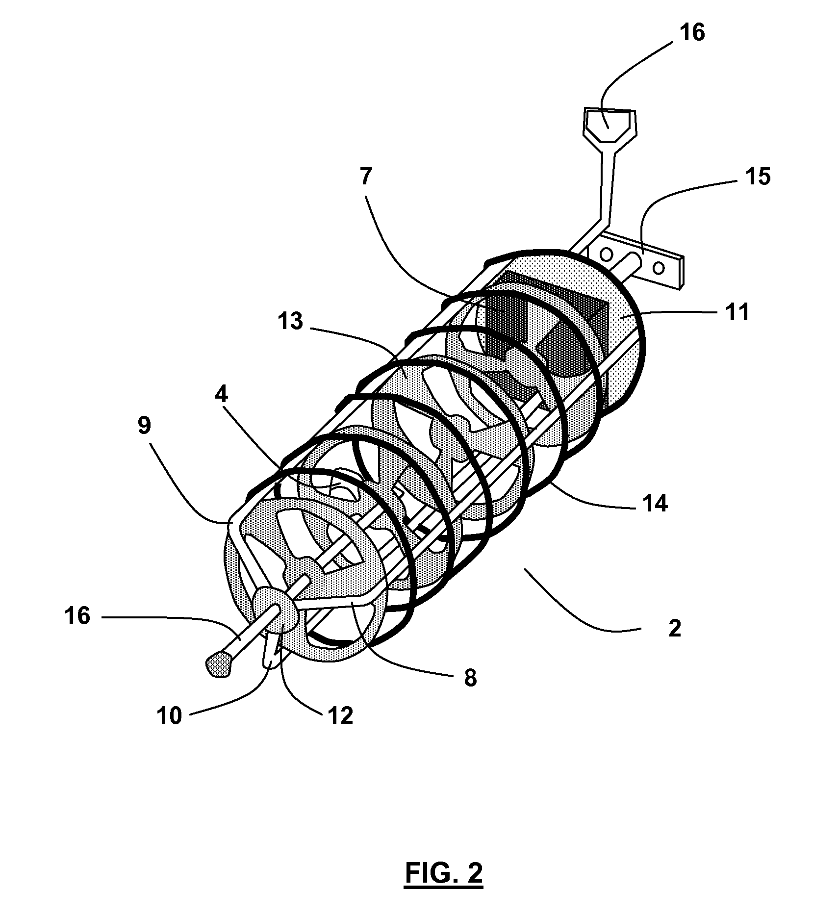
[0012]Referring to FIG. 1, an illumination balloon consistent with the present invention comprises an inflatable bladder 1 that envelops an assembly 2. The assembly comprises a frame 3, a plurality of light sources (4, 5, 6), and a mechanical fan 7. The frame 3 comprises three hollow tubes (8, 9, 10) mounted to a base plate 11 and welded to a ring 12 at the top of the frame 3, lamp base mounting plates 13, ring supports 14, pole mount 15, and an extension rod 16.

[0013]The inflatable bladder 1 may be constructed of any flexible, translucent material.

[0014]Preferably, the inflatable bladder 1 is made from Odyssey III™ coated polyester manufactured by MarChem CFI. In preferred embodiments of the present invention, the inflatable bladder 1 measures 4′ in diameter and 39″ in height, and at the base of the inflatable bladder 1, a 12″ diameter opening is cut (not shown) which is reinforced along the edges of the opening by a 3″ strip of vinyl. The base of the inflatable bladder 1 may be at...


PUM


Abstract

An illumination balloon which has an inflatable bladder surrounding an assembly that includes a frame comprised of hollow tubes, lighting sources, and mechanical fan for inflating said bladder. The lighting sources are staggered along the frame so that each is unimpeded from the fixtures and bulbs of the other lighting sources. The mechanical fan does require a transformer to step up or step down the voltage received from an external power supply. Wiring to energize the lighting sources and mechanical fan are threaded through the hollow tubes of the frame.

Description

CROSS-REFERENCE TO RELATED APPLICATIONS[0001]Not Applicable.STATEMENT REGARDING FEDERALLY SPONSORED RESEARCH[0002]Not Applicable.BACKGROUND[0003]1. Field of Invention[0004]The present invention relates to devices used to provide illumination. In particular, the present invention relates to balloons used for illumination purposes.[0005]2. Description of Related Art[0006]There is a need in many technical fields for illumination of remote, outdoor areas during the nighttime. For example, in the field of oil and gas drilling, drilling operations typically occur 24 hours per day in remote areas. Strong illumination of the drilling rig and surrounding area is essential if such operations are to be conducted safely in the nighttime. All variety of portable lighting means are used at drill sites to accomplish this illumination. Examples include portable floodlights and light towers.[0007]Another example is a illumination balloon. Illumination balloons are known and certain embodiments of il...

Claims


Application Information

Patent Timeline
Patent Type & Authority Patents(United States)
IPC IPC(8): F21V33/00
CPCF21V3/026F21V17/007F21W2131/10F21Y2101/02F21Y2115/10
Inventor ALLEN, CHRISPACKARD, CLIFFORD
Owner A&P SUPPORT
Why Eureka
Try Eureka