Method of illuminating a 3D object with a modified 2D image of the 3D object by means of a projector, and projector suitable for performing such a method

a technology of 3d objects and projectors, applied in the field of methods of illuminating 3d objects, can solve the problems of not readily suitable prior art methods for an automized effect illumination of 3d objects, the way in which images of 3d objects are obtained is complicated, and the method of prior art requires man-made editing of images, etc., to achieve the effect of low cost, low cost and simple operation of the projector

Inactive Publication Date: 2013-12-31
KONINK PHILIPS ELECTRONICS NV
View PDF16 Cites 1 Cited by
  • Summary
  • Abstract
  • Description
  • Claims
  • Application Information

AI Technical Summary

Benefits of technology

[0007]b. determining one or more 2D image regions on the 2D image corresponding to the one or more features selected from the group consisting of (i) regions with specific textures, (ii) shadow regions, (iii) reflective regions, (iv) color regions and (v) other regions at the 3D object;c. modifying at least one of the one or more 2D image regions of the 2D image by changing one or more features selected from the group consisting of (i) color and (ii) brightness to obtain one or more modified image regions of the modified 2D image;d. illuminating the 3D object by the projector by projecting the modified 2D image on the 3D object, wherein the projections of the one or more modified image regions at the 3D object substantially overlap with one or more of the regions at the 3D object.Advantageously, the method provides an alternative method, which may relatively easily allow the creation of modified images with which the 3D object can be illuminated. Further, it may allow fully automated illumination, with modified images, of 3D objects, such as 3D art objects, which are illuminated with 2D images of such objects. In addition, complicated acquirement of images is not necessary.
[0009]Advantageously, the projector easily provides the possibility to perform the method of the invention. It may also allow the use at different places and illumination of different 3D objects, without complicated alignment of projector and object and without elaborate acquirement of images of the 3D object.
[0010]With the method and projector according to the invention, 3D objects, such as 3D art objects, may be illuminated with a manipulated image of the object itself, thereby providing spectacular effects, allowing a kind of living art, and adding an additional art dimension to the 3D art object. Such image(s) may be changed in time, subjected to random or predetermined manipulations, etc.
[0030]In another embodiment, the projector may further comprise a single-lens reflex unit arranged between the panel and the lens arranged to allow an optical axis of the projector downstream of the single-lens reflex unit to substantially coincide with an optical axis of the image sensor downstream of the single-lens reflex unit. The single-lens reflex unit may be constructed to arrange a mirror between the final lens and the panel and redirect the light to the image sensor. In this way, the image sensor may cover substantially the same (range) as the projector does with its beam of light. After having captured the 2D image, the mirror may be removed and the projector may project the modified 2D image, similar to the principle of the single-lens reflex camera in which a viewer sees the same image as that captured by the camera.
[0032]In a specific embodiment, the light source comprises one or more monochromatic light sources. Such light source may especially comprise one or more LEDs (light emitting diodes). In yet another embodiment, the light source comprises an ultra-high pressure (UHP) lamp. Hence, in a specific embodiment, the light source can produce only one color of light, but the color is adjustable. This can for example be done with red, green and blue LEDs. In this way, the optics of the projector may become relatively simple: only one panel with a large aperture may be used, and no color filters or color splitting specific optics are necessary. An advantage thereof is a high transmission and a cheap single panel solution. The color can be changed over time. In yet another embodiment the light source comprises a color wheel and a UHP lamp.

Problems solved by technology

A disadvantage of the prior art systems is the rather complicated way in which images of the 3D object are obtained, such as for instance by a complete scanning of the 3D object, acquiring a 3D model, etc.
A further disadvantage is that the methods of the prior art need man-made editing of the images made of 3D object.
Therefore, the prior art methods are not readily suitable for an automized effect illumination of 3D (art) objects.

Method used


Image

  • Method of illuminating a 3D object with a modified 2D image of the 3D object by means of a projector, and projector suitable for performing such a method
  • Method of illuminating a 3D object with a modified 2D image of the 3D object by means of a projector, and projector suitable for performing such a method
  • Method of illuminating a 3D object with a modified 2D image of the 3D object by means of a projector, and projector suitable for performing such a method

Examples


Embodiment Construction

[0039]To describe the invention in more detail, first a 3D art object is described in detail. This 3D art object is used as an example to describe and illustrate the invention.

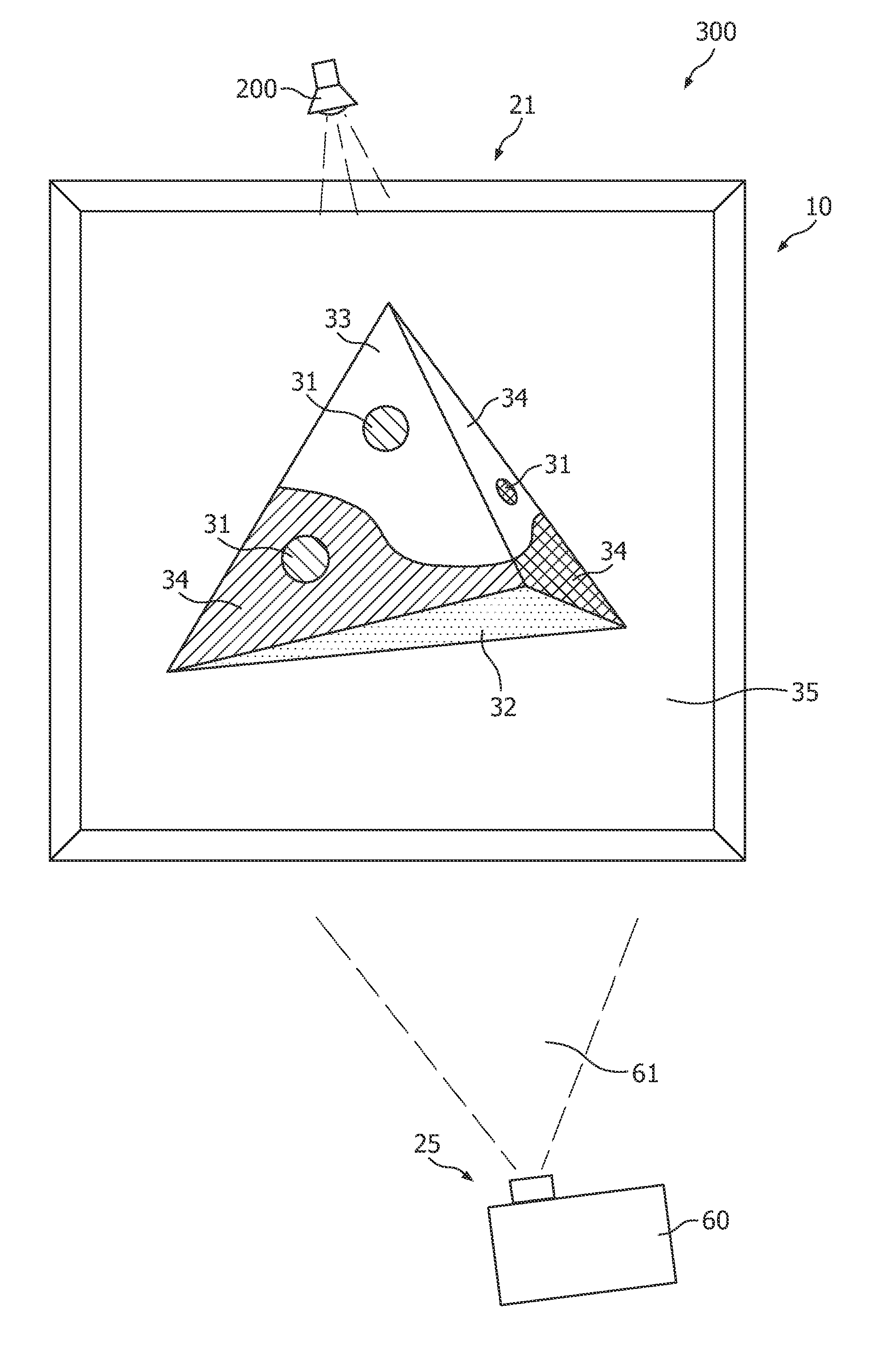
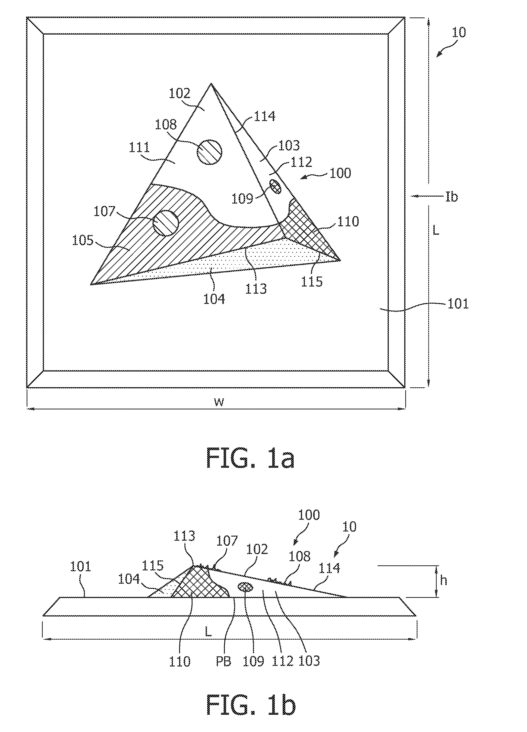
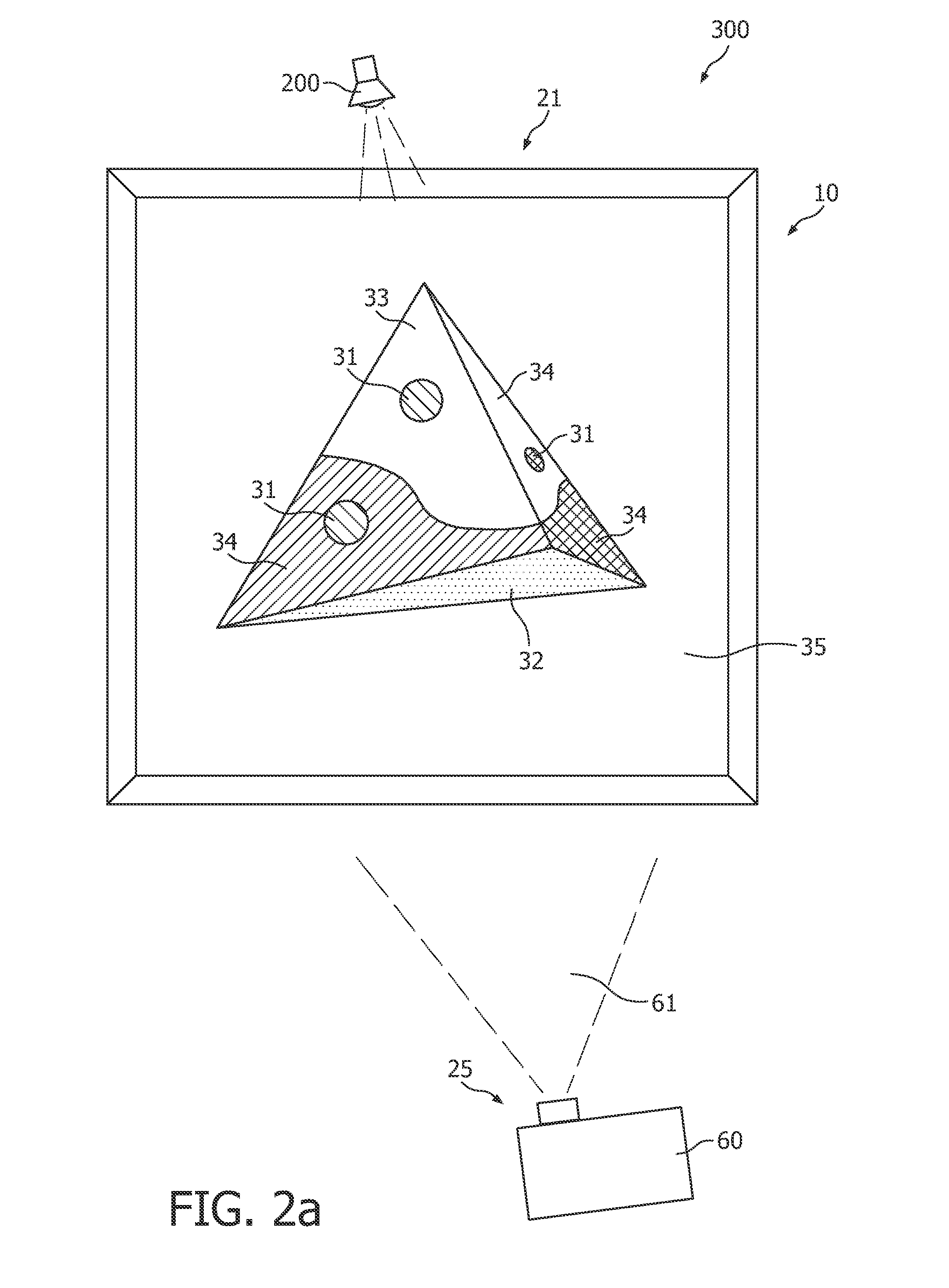
[0040]FIGS. 1a and 1b schematically show this 3D object, indicated with reference 10, in a front view and a side view, respectively. 3D object 10 comprises a flat background 101, which in this example may be black. It could for instance be a stretched canvas on a frame or a missive board. On this flat black background 101, a distorted trigonal pyramid 100 is attached. This pyramid 100 has 3 faces, and is attached with its bottom (PB) to the background 101. The pyramid has one large face 102, one smaller face 104 and another smaller face 103. Faces 102 and 103 have an edge 114, faces 102 and 104 have an edge 113 and faces 103 and 104 have an edge 115.

[0041]The pyramid 100 has a number of colors and structures on it. Reference number 105 refers to a colored region of face 102, reference number 110 refers to a co...


PUM


Abstract

The invention provides a method of illuminating a 3D object 10 with a modified 2D image of the 3D object 10. Further, the invention provides a dedicated projector 40 for performing this method. This projector 40 further comprises an image sensor 60 to capture a 2D image of the object, which may, after modification into the modified 2D image, be projected by the projector 40 on the 3D object 10.

Description

FIELD OF THE INVENTION[0001]The invention relates to a method of illuminating a 3D object, especially a 3D art object, with a modified 2D image of such a 3D object, by means of a projector which (in use) projects the modified 2D image of the 3D object on the 3D object. The invention further relates to a projector that is suitable for performing such a method.BACKGROUND OF THE INVENTION[0002]Objects illuminated with specific designs or graphics are known in the art. US 2003 / 0034974 for instance describes a computer-implemented method of animating a 3D physical object by first acquiring a 3D graphics model of the object. The concept of the invention described in this document is to replace a physical object having inherent color, texture, and material properties with a neutral object illuminated by projected imagery, thus reproducing the original or alternative appearance directly on the object. In this approach, the desired visual properties of the object are effectively “lifted” int...

Claims


Application Information

Patent Timeline
Patent Type & Authority Patents(United States)
IPC IPC(8): H04N9/47
CPCG03B21/00G03B15/02
Inventor BERGMAN, ANTHONIE HENDRIKVAN GORKOM, RAMON PASCALKRIJN, MARCELLINUS PETRUS CAROLUS MICHAEL
Owner KONINK PHILIPS ELECTRONICS NV
Why Eureka
Try Eureka