
Apparatus and method for cooperatively transmitting downlink between base station and relay station

a technology of relay station and relay station, which is applied in the field of cooperative transmission of downlink signal to terminal, can solve the problems of reducing performance, affecting transmission efficiency, and affecting transmission efficiency, so as to prevent the waste of wireless resources and prevent the degrade of transmission efficiency

Inactive Publication Date: 2013-12-31
LG ELECTRONICS INC
View PDF7 Cites 2 Cited by
  • Summary
  • Abstract
  • Description
  • Claims
  • Application Information

AI Technical Summary

Benefits of technology

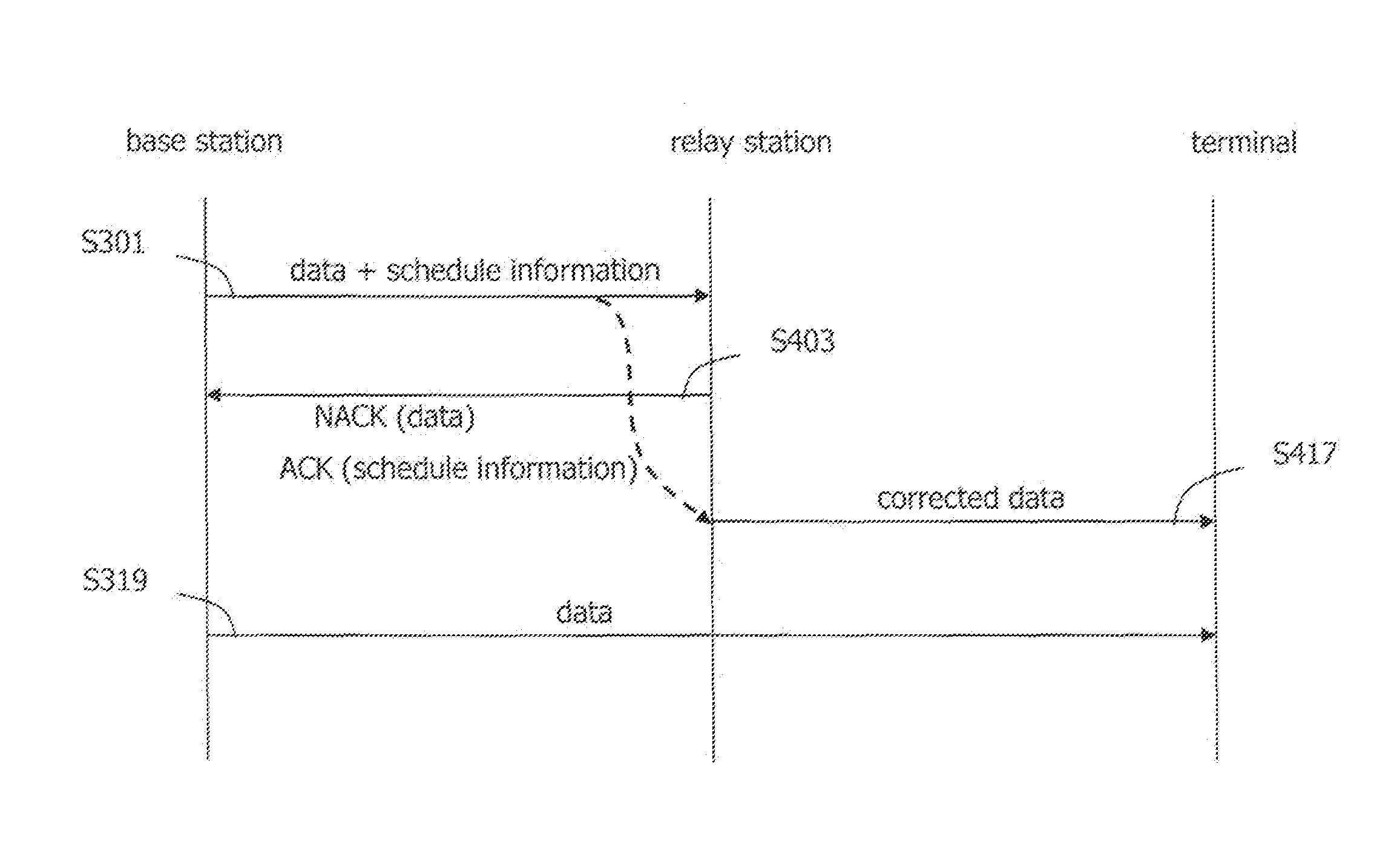
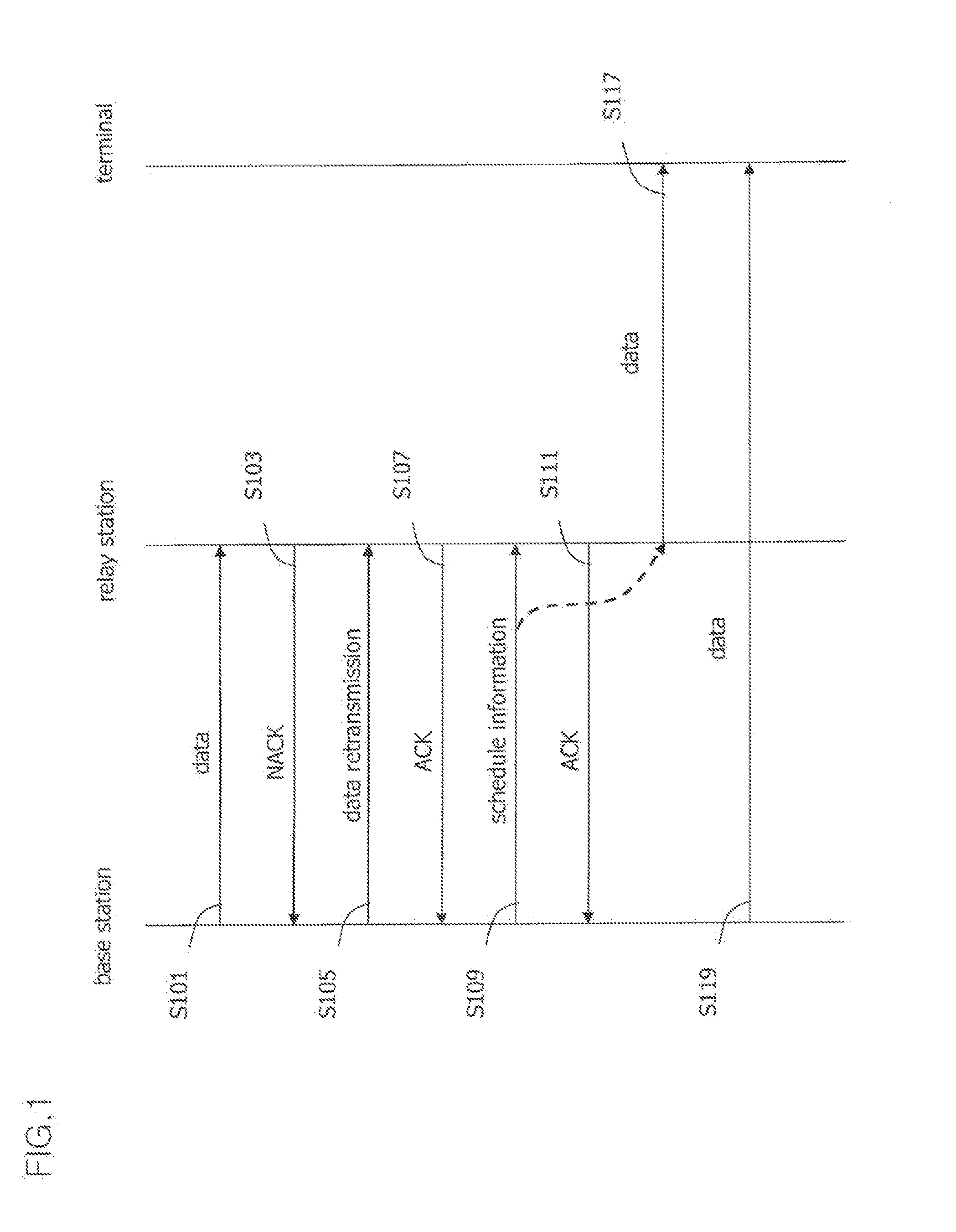
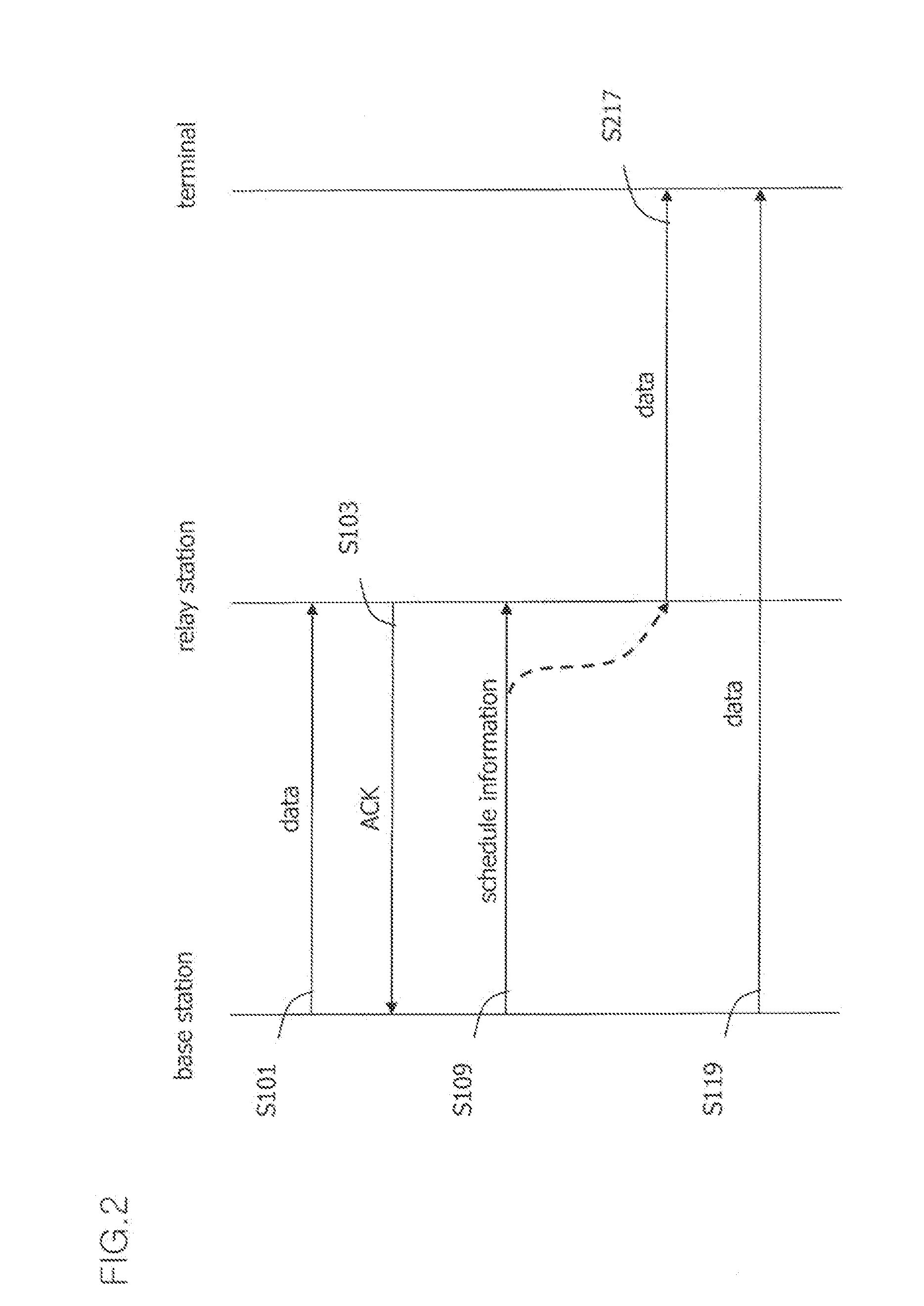
The present invention provides a way for a base station and a relay station to work together to transmit data. Even if there are errors in the communication between the two, the invention allows for the transmission of scheduling information to the relay station from the base station. This helps to prevent wasted resources and ensures efficient transmission of data to the terminal. It also helps to avoid delays in signal transmission.

Problems solved by technology

Since a signal between BS-RS may be different from a signal between RS-MS, interference may occur when using the same wireless resources.
This may lower the performance.
However, the cooperative silencing technique may have the following problems.
Firstly, since the BS is in an idle state using no wireless resources at a transmission section between the RS and the MS, a resource loss may occur.
However, in a substantial communication environment, the RS may not successfully receive cooperative transmission data transmitted from the BS.
[7] In spite of this problem, the conventional art has proposed no method for preventing a transmission error in a link between the BS and the RS.
Since there is no consideration about a transmission error in a link between the BS and the RS in the conventional art, when the RS has not successfully received data transmitted from the BS, wireless resources pre-allocated so as to be transmitted to the MS may be wasted.
Furthermore, since the BS and the RS do not perform an effective cooperative transmission, transmission efficiency to the MS may be lowered and long time delay may occur.

Method used


Image

  • Apparatus and method for cooperatively transmitting downlink between base station and relay station
  • Apparatus and method for cooperatively transmitting downlink between base station and relay station
  • Apparatus and method for cooperatively transmitting downlink between base station and relay station

Examples


Embodiment Construction

[0040]The present invention is applied to a mobile communications system, and more particularly, to an IEEE802.16m system or an E-UMTS (Evolved Universal Mobile Telecommunications System) evolved from a UMTS (Universal Mobile Telecommunications System), etc. However, the present invention is not limited to this, but may be applied to all types of communications systems and communication protocols to which the techniques of the present invention may be applicable.

[0041]It will also be apparent to those skilled in the art that various modifications and variations can be made in the present invention without departing from the spirit or scope of the invention. Thus, it is intended that the present invention cover modifications and variations of this invention provided they come within the scope of the appended claims and their equivalents.

[0042]Though terms including ordinal numbers such as a first, a second, etc. may be used to explain various components, the components are not limite...


PUM


Abstract

The present invention relates to an apparatus and method for cooperatively transmitting a downlink between a base station and a relay station. According to one embodiment of the present invention, a method for cooperatively transmitting a downlink signal between a base station and a relay station in a wireless broadband communication system comprises the steps of: receiving cooperative transmission data from the base station and transmitting an acknowledgement message corresponding to the cooperative transmission data to the base station; receiving scheduling information for transmitting the cooperative transmission data by a cooperative transmission scheme; and transmitting the data cooperative transmission data to a terminal in reference to the scheduling information.

Description

[0001]This application is the National Stage filing under 35 U.S.C. 371 of International Application No. PCT / KR2010 / 000399, filed on Jan. 21, 2010, which claims the benefit of U.S. Provisional Application Ser. No. 61 / 146,648, filed on Jan. 22, 2009, the contents of which are all incorporated by reference herein in their entirety.TECHNICAL FIELD[0002]The present invention relates to a wireless communication system using a relay station, and more particularly, to an apparatus and method for cooperatively transmitting a downlink signal to a terminal by a base station and a relay station.BACKGROUND ART[0003]In the next generation wireless communications system, a relay station (RS) is being introduced so as to increase cell coverage and to enhance a data transmission rate.[0004]In the conventional wireless communications system using a relay station, there are not only wireless resources which consist of time or a frequency between a base station (BS) and a mobile station (MS), but also...

Claims


Application Information

Patent Timeline
Patent Type & Authority Patents(United States)
IPC IPC(8): H04B7/14H04B7/005H04L12/28H04J1/10
CPCH04W92/10H04W88/04H04L2001/0097H04W84/047H04B7/155H04W72/1289H04W28/04H04L1/1854H04W28/06H04W72/23H04L1/16H04B7/15592H04B7/024H04W72/1273
Inventor SEO, HAN-BYULCHOI, YOUNG-SEOB
Owner LG ELECTRONICS INC
Learn More