
Electric grilling appliance

a grilling appliance and electric technology, applied in the field of new electric grilling appliances, can solve the problems of large amount of heat generated, high temperature, and direct contact between the grilling surface and the food being grilled, and achieve the effect of efficient heating of the appliance, not overheating, and not overheating or burning or drying out the food being cooked

Inactive Publication Date: 2014-01-07
SORENSON WALLY B +1
View PDF50 Cites 13 Cited by
  • Summary
  • Abstract
  • Description
  • Claims
  • Application Information

AI Technical Summary

Benefits of technology

The electric grilling appliance described in this patent has two main advantages: it is efficient in heating food to a specific temperature without overwhelming it with hot air, and it allows for smoking of the food without needing a large amount of air flow. This means that the food is cooked quickly and effectively, while also giving it a unique flavor through the smoking process.

Problems solved by technology

However, grilling has traditionally been performed with fire to achieve the desired grilled food flavor, but the use of fire has a number of fairly evident drawbacks, including, but not limited to, the presence of an open flame, the large amount of heat that is generated and creates high temperatures (that is dissipated into the immediate environment), and the smoke that results when juices from the food come into contact with the flame or the heated surfaces of the grill apparatus.
While some indoor grilling apparatus, such as those sold under the GEORGE FOREMAN trademark, have become popular, these types of grilling apparatus generally have an open character that releases a large amount of heat into the immediate environment of the grilling apparatus and exposes hot surfaces to the user and those around the user during the cooking process.
Further, the direct contact between the grilling surfaces and the food being grilled can require a significant amount of clean up.

Method used


Image

  • Electric grilling appliance
  • Electric grilling appliance
  • Electric grilling appliance

Examples


Embodiment Construction

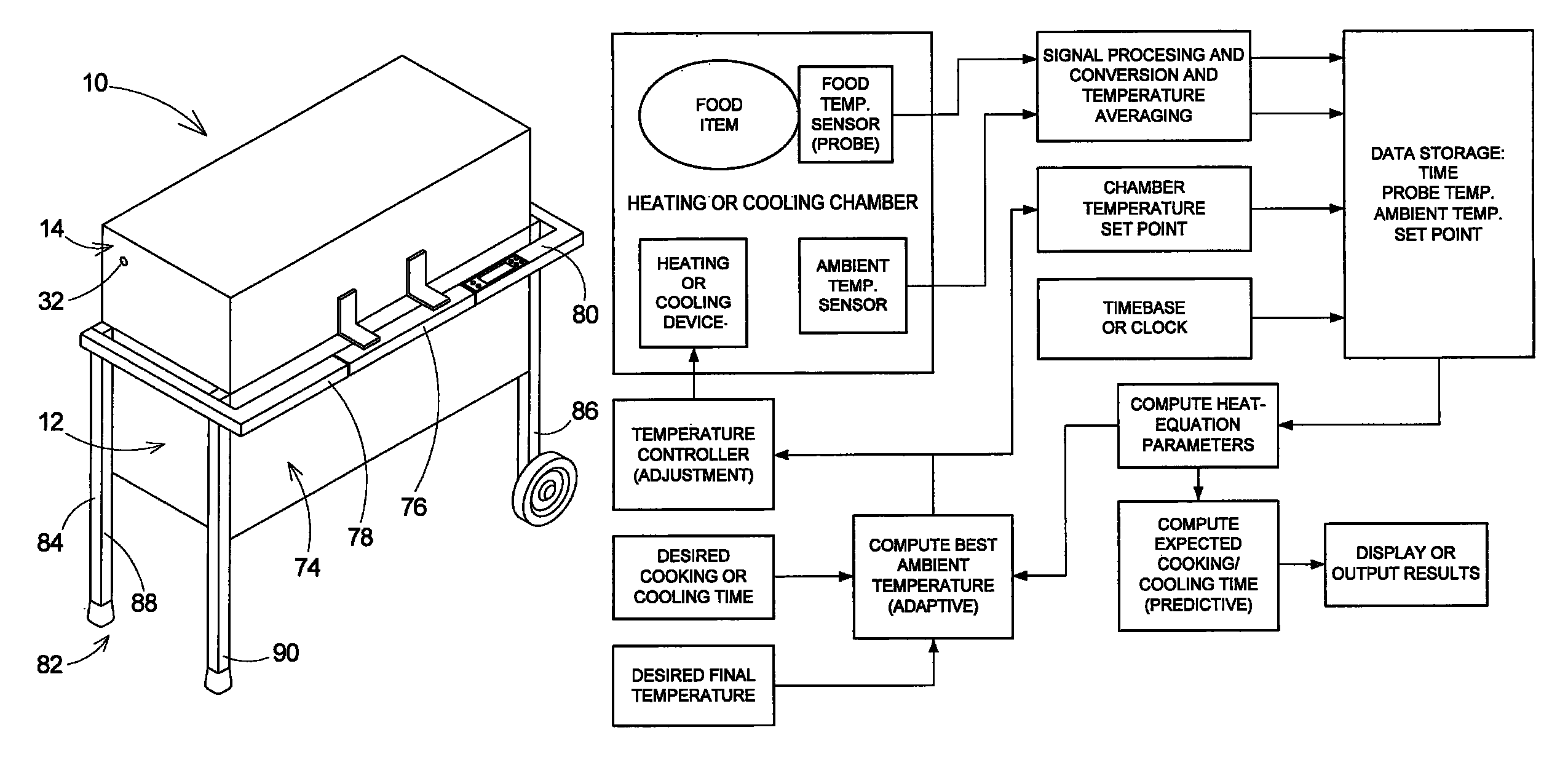
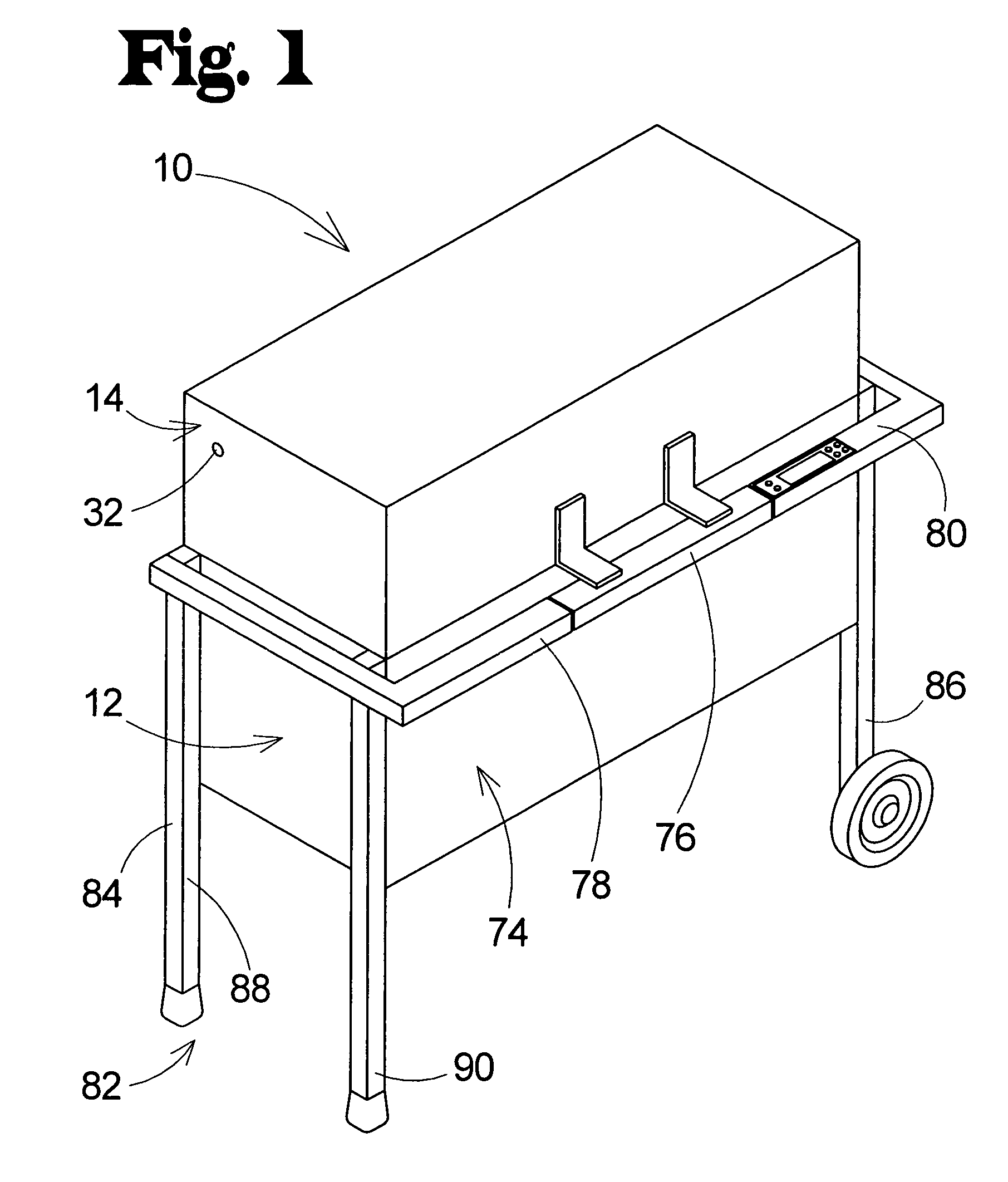
[0034]With reference now to the drawings, and in particular to FIGS. 1 through 12 thereof, a new electric grilling appliance embodying the principles and concepts of the present invention and generally designated by the reference numeral 10 will be described.

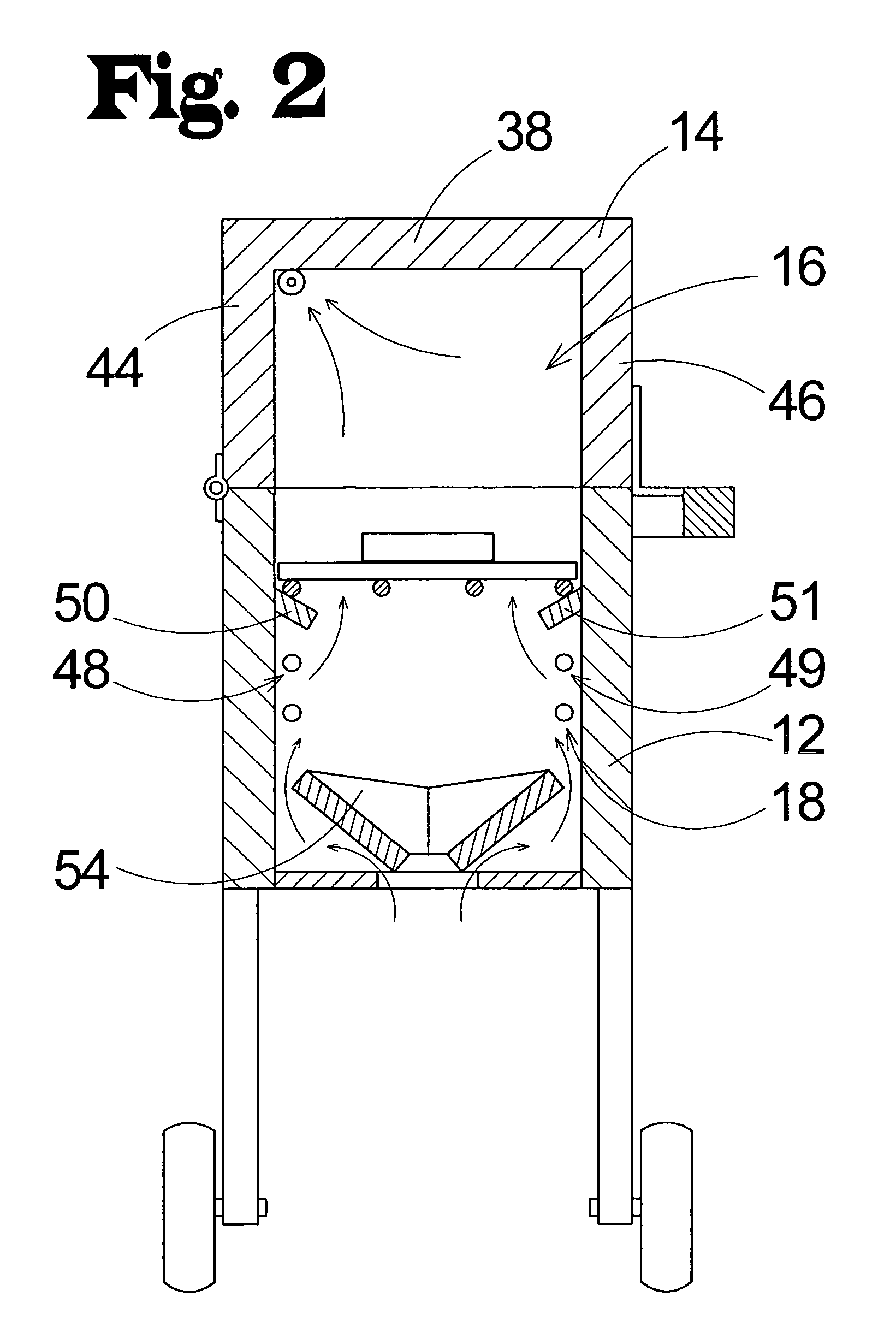
[0035]As illustratively shown in FIGS. 1 through 5, the food heating and grilling appliance 10 of the invention generally includes a chamber portion 12 and a lid portion 14 that define a heating chamber 16 for receiving an item of food to be heated, in which a heating apparatus 18 is positioned.

[0036]The chamber portion 12 defines a lower section of the heating chamber 16, and has an upper opening 20 that opens into the heating chamber 16. In the illustrative embodiment of the invention, the chamber portion 12 may comprise a perimeter wall 22 that defines the upper opening 20 and extends about the heating chamber 16. The perimeter wall 22 comprises a pair of side walls 24, 26, and a pair of end walls 28, 30. The walls 22, 24, 26...


PUM


Abstract

A heating appliance comprises a chamber portion defining a heating chamber, a lid portion, a heating apparatus to heat air in the heating chamber, a food temperature sensor to sense an internal temperature of an item located in the heating chamber, a user interface configured to receive designation of a desired time of completion of heating of the item from the user, and a control circuit configured to control the supply of power to the heating apparatus. The control circuit is in communication with the temperature sensor and the user interface. The control circuit may control the heating apparatus so that the internal temperature of the item reaches a predetermined temperature at the desired time of completion designated by the user. The control circuit may control the heating apparatus so that the internal temperature of the item is maintained at a predetermined temperature for a predetermined period of time before an end of the desired time of completion.

Description

REFERENCE TO RELATED APPLICATION[0001]This application is a continuation-in-part of application Ser. No. 10 / 960,654, filed Oct. 7, 2004, now U.S. Pat. No. 7,339,137, which is hereby incorporated by reference in its entirety.BACKGROUND OF THE INVENTION[0002]1. Field of the Invention[0003]The present invention relates to cooking appliances and more particularly pertains to a new electric grilling appliance for cooking food cleanly and effectively with a minimum of smoke generation that permits the use of the appliance in enclosed spaces.[0004]2. Description of the Prior Art[0005]Grilling is a highly desirable way of cooking food as grilling imparts a unique taste and health benefits to the food that are difficult to achieve with other methods of food preparation. However, grilling has traditionally been performed with fire to achieve the desired grilled food flavor, but the use of fire has a number of fairly evident drawbacks, including, but not limited to, the presence of an open fla...

Claims


Application Information

Patent Timeline
Patent Type & Authority Patents(United States)
IPC IPC(8): H05B1/02F24C7/08A47J37/07A21B1/40A47J37/06
CPCA47J31/52A47J37/0709A47J36/32
Inventor SORENSON, WALLY B.SORENSON, ADAM
Owner SORENSON WALLY B
Learn More