[0012]The present invention provides a tillage system, which can be used by farmers to till a field in spring prior to planting and in fall after harvesting farm crops for primary tillage. The system of this invention includes a plurality of spaced first deep tilling tines that plough the field deep along planting rows. A plurality of spaced rows of shallow tilling tines positioned in front of and mostly behind the deep tilling tines in the moving direction of the tiller smoothen the ground adjacent to the deep tilled location and clear the debris on the land segments between the deep tilled planting rows. This creates a field that appears tilled, rather than a field which, despite having been deep tilled, retains unsightly plant stocks and weed residue between the deep tilled locations. The last row of shallow tilling coulter is always provided that has a ruffled disk pushes debris such as plant stocks into the ground, thereby mixing and anchoring tilled soil between the deep-tilled groves and preventing water run-off and consequent soil erosion. A third set of tools has a series of harrows, cage rollers or packer wheels may be used behind the shallow tilling ruffled disks to smoothen the soil surface.
[0013]The tillage system has a tool bar that carries a plurality of deep tilling tines with inserted hardened steel projections adapted to till the ground along a plurality of planting rows. Due to the large diameter of these deep-tilling tines, the depth of till may be adjusted from about 5 inches to 12 inches for fall tilling and from 5 to 8 inches for spring tilling. Such an adjustment is easily made by changing the location of an individual attachment bar loaded by spring, air pressure or a hydraulic ram, which connects the deep tilling cutters to the tool bar. This first set of deep-tilling tines may be driven at a tilling ground speed selected by the operator. When a deep tilling tine comes across a hard object such as rock, the loading mechanism yields, thereby preventing damage to the deep tilling tines. The deep tilling tines unearth weeds and bring to the top of the soil any plant roots present there within. As a result of this deep tilling, deep grooves are formed in the field. These grooves are bound by two mounds of soil, one mound being located to either side of the deep groove. The deep tilling tines may be made with a number of structural configurations including toothed tines with lateral and radial extensions, three dimensionally formed ruffled coulters and other geometric shapes all designed to deep till to a depth of 5 to 12 inches. If deeper depth is required for different soil types, the diameter of the deep tillage tine will be increased. Unless disturbed, the land segments between the deep grooves would remain essentially untilled and exhibit an unsightly appearance. A conventional tilling system does not have these shallow tilling tines or coulters such as that disclosed in U.S. Pat. No. 7,575,066 to Bauer strictly produces the tilling of deep grooves at the plant rows. Irrigation of the field occasioned by rain or artificial irrigation causes water to collect within the deep grooves. The deep grooves have limited volume, which limits their ability to absorb water into the field. Moreover, the mounds formed to either side of the grooves typically contain high quality topsoil, which tends to be washed off, carrying fertilizer that was previously applied, and producing soil erosion. The ability of water to be absorbed in the untilled portion of the field between the deep tilled grooves is very limited and most of the water supplied by rain or artificial irrigation runs off from the field due to soil compaction without benefiting the planted crop.
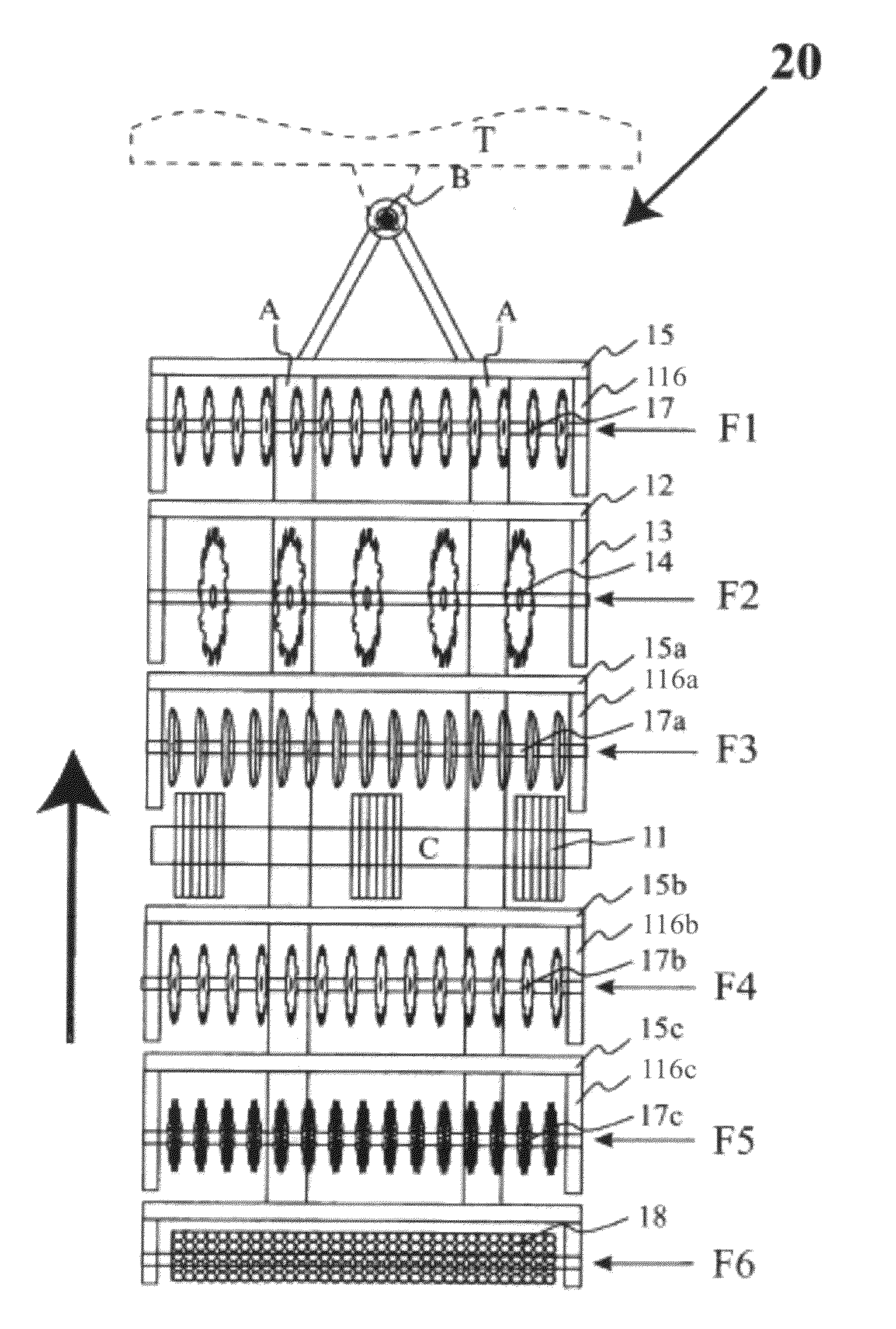
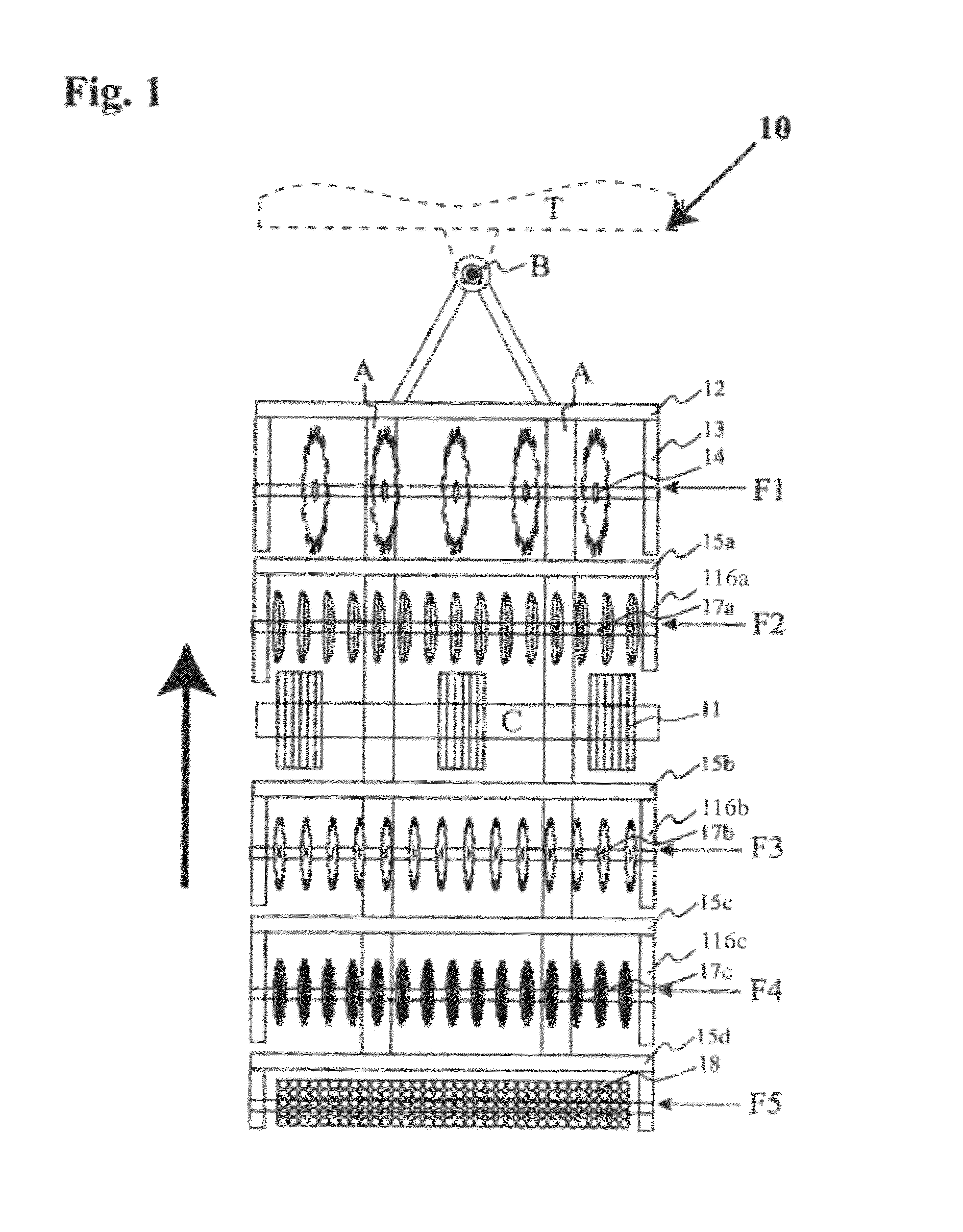
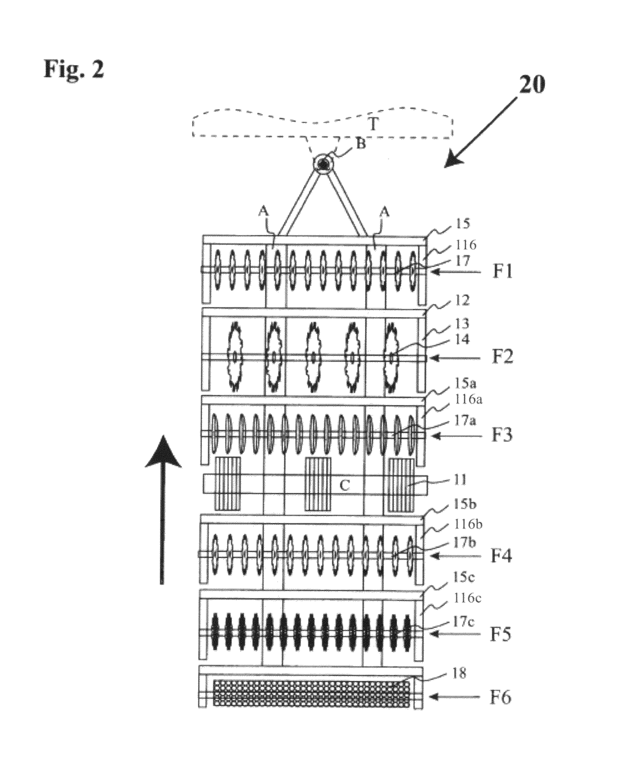
[0014]The present invention uses plurality of sets of shallow, nominally vertical coulters that are placed directly behind as well as in front of the deep tilling tines at adjustable, selected distances. The shallow tilling coulters may be dispersed in several rows, some in front of the deep tilling tines and some always behind the deep tilling tines and may have several shapes. The coulters may be in the form of toothed tine rotors or rotors with a ruffled structure. These shallow tilling coulters have no specific spacing relation to the spacing of the deep tilling tines, and are generally present in a much greater number than the number of deep tilling tines employed. When a shallow tilling coulter is placed in front of the deep tilling tines, it functions to size the crop residue and clear the ground facilitating smooth operation of the deep tilling tines. All the shallow tilling tines are run at the ground speed of the tillage system. The depth of till for the shallow till coulters is adjusted by moving the coulter wheels up or down. This adjustment is effected by the operator of the tillage system, and is nominally in the 1 to 4 inches range. The shallow tilling coulters thus clear most of the plant debris in the field between the deep tilled grooves. They also stir and mix the soil. Preferably, the shallow tilled portions of the field tilled by the coulters only disturb the soil slightly providing space for the water absorption from rain or artificial irrigation. Water run-off is substantially prevented. The field provided by the tilling practice of the present invention exhibits a neat appearance characterized by the removal of perennial weeds previously extant between the deep tilled grooves. The tool bar may be increased in width by adding a set of hydraulic folding wings that carry the similar arrangement of tines.
[0015]For example, a typical tillage system has a first row of deep tilling tines, the second row of curved coulters designed to displace the tilled soil laterally perpendicular to the movement direction. These curved coulters may be lifted off above the ground when not needed. A third row of shallow tilling toothed coulters is provided the orientation of which is set from zero to 10 degrees with respect to the travel direction of the tillage system. The inclined toothed shallow tilling coulters displace soil laterally eliminating mounds and mixing plant debris with the soil in a manner similar to curved coulters and may function better in some soils or crop fields. A last fourth row of ruffled disks shallow tilling coulters is always provided to mix the plant debris into the tilled ground, binding the soil from water erosion. A fifth row of soil surface smoothening tools such as harrow tools, cage roller tool or packer wheels may be provided. A shallow tilling toothed coulter may be additionally added in front of deep tilling tines to size tall plant debris in the field enabling tilling deep tilled grooves in the field more easily. The number of shallow tilling coulter and its order may be changed according to the needs of field being tilled.
[0016]Advantageously, the tillage system of the present invention leaves behind a clean tilled field with very little or no unsightly weeds and a plurality of deep tilled grooves for row planting of a crop. The deep tilled grooves do not have mounds on either side thereof due to the tilling action of the shallow tilling coulters. In addition, the field surface is well leveled and free from water running channels, a key feature that prevents water run off.
[0025]whereby the shallow tilling tines smoothen the tilled soil surface, eliminating the mounds formed on the sides of the deep groove generated by the deep tilling tines, and remove plant debris between the deep tilled grooves, creating a clean tilled field appearance, so that the shallow tilled regions provide sufficient water absorption for rain or irrigation water, substantially eliminating water run-off, as well as soil erosion.

