Electrical accessory mounting device for a saddle-type vehicle

a technology of electric accessory and mounting device, which is applied in the direction of other supporting devices, vehicle components, cycle equipment, etc., can solve the problem of difficulty for a rider to visually check the navigation apparatus

Active Publication Date: 2014-01-14
HONDA MOTOR CO LTD
View PDF6 Cites 46 Cited by
  • Summary
  • Abstract
  • Description
  • Claims
  • Application Information

AI Technical Summary

Benefits of technology

[0009]Accordingly, in view of the problems above, it is an object of the present invention to provide an electrical accessory mounting device for a saddle-type vehicle capable of adjusting the position of the electrical accessory such that a rider can easily check the electrical accessory visually.
[0017]According to the first aspect of the present invention, the mounting device is able to set an angle of said holding portion to a predetermined angle by movement of said holding portion, thus allowing the electrical accessory to be adjusted to an easily viewable position where other members do not interfere.
[0018]According to the second aspect of the present invention, the mounting device is able to adjust the position and angle of the electrical accessory by moving the electrical accessory either in parallel or from back to front so as to rotate the electrical accessory.
[0019]According to the third and fourth aspects of the present invention, the mounting device is able to set the angle of the holding portion by engaging the guides with the movement portions.
[0020]According to the fifth and sixth aspects of the present invention, the mounting device is able to set the angle of the holding portion by a simple structure in which the long hole and the screw are engaged with each other.
[0021]According to the seventh to tenth aspects of the present invention, the mounting device is able to set the angle of the holding portion while allowing the holding portion to move, since a pair of said guides are arranged in the crossing directions.

Problems solved by technology

However, it is difficult for a rider to visually check the navigation apparatus while riding a two-wheeled vehicle because the navigation apparatus is arranged along the fuel tank and thus the rider must look down at the navigation apparatus.

Method used


Image

  • Electrical accessory mounting device for a saddle-type vehicle
  • Electrical accessory mounting device for a saddle-type vehicle
  • Electrical accessory mounting device for a saddle-type vehicle

Examples


first embodiment

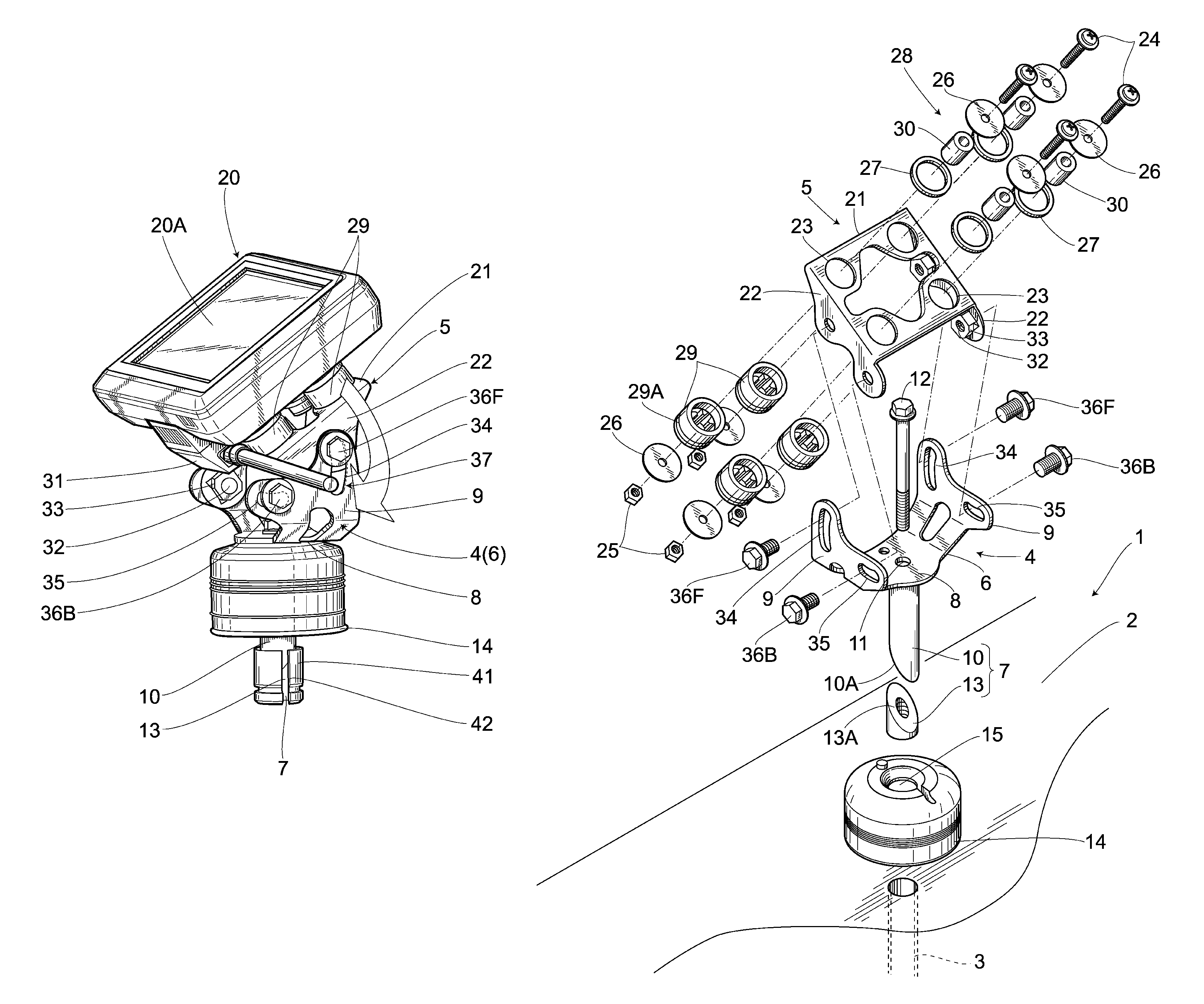
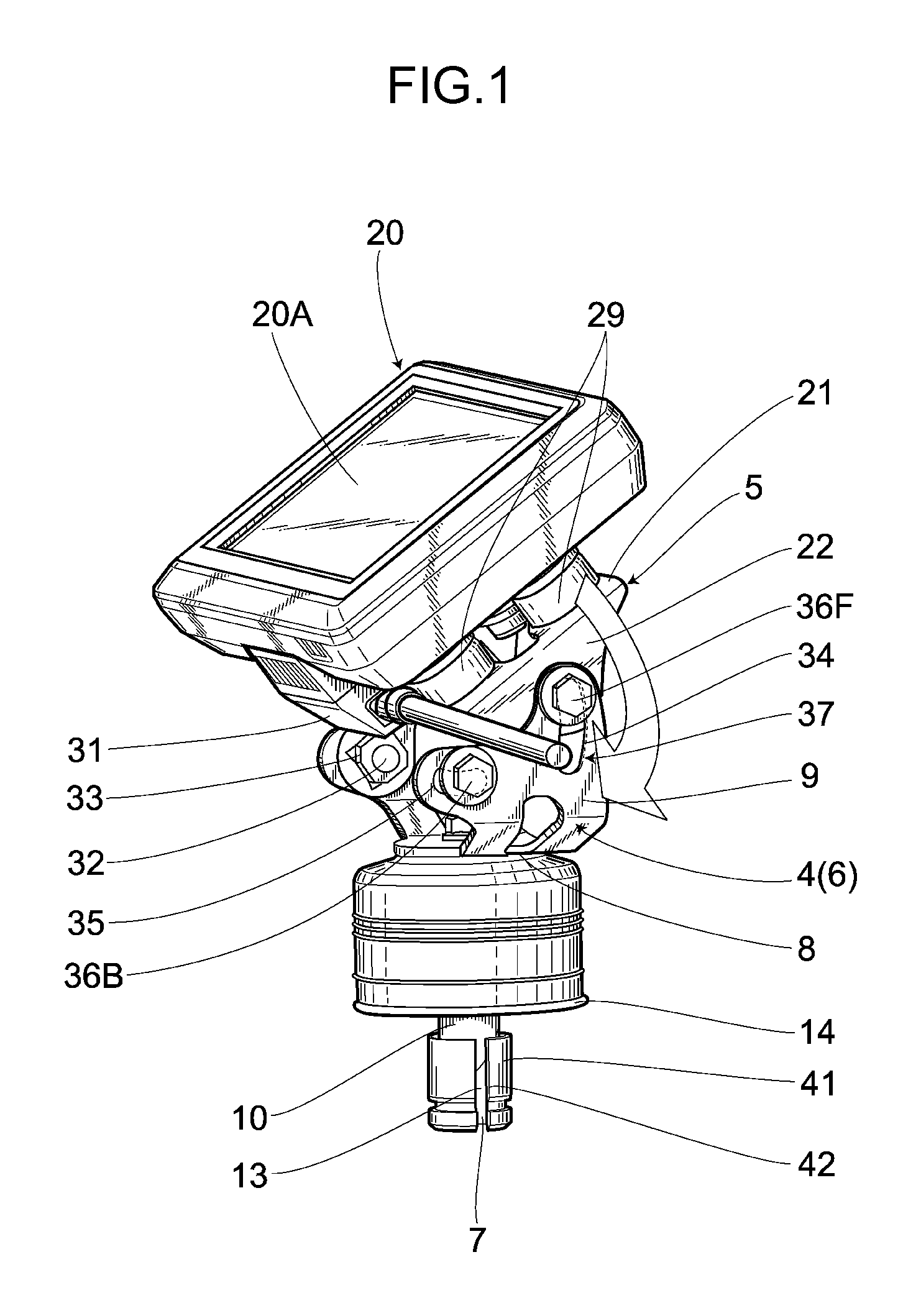
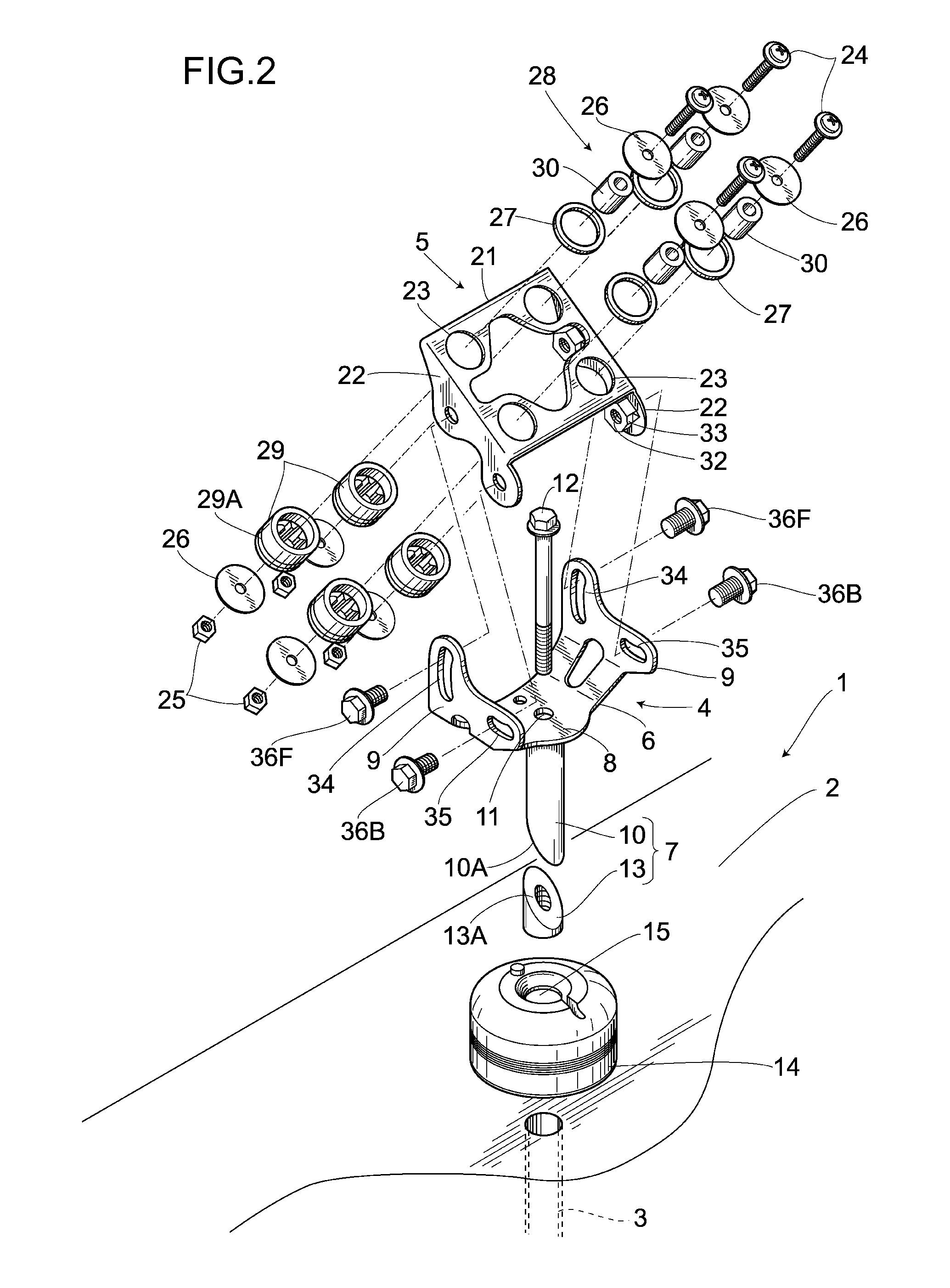
[0046]As shown in FIG. 1 to FIG. 5, an electrical accessory mounting device of the present embodiment comprises: a steering stem pipe 3 located at the substantial rotational center of a steering portion 2 for a saddle-type vehicle 1 as a two-wheeled vehicle; a metallic fixture 4 fixed on the steering stem pipe 3; and a bracket 5 as a holding portion provided on the fixture 4 in such a manner that the position of the bracket 5 can be adjusted.

[0047]The fixture 4 includes a receiving portion 6 receiving the bracket 5 in a position-adjustable manner and an insertion portion 7 which is inserted into the steering stem pipe 3 and then fixed thereto. The receiving portion 6 and the insertion portion 7 are metallic.

[0048]The receiving portion 6 has a side plate 9 on both lateral sides of a base 8 and is formed in a U-shape whose upper portion is open. Further, the insertion portion 7 includes an insertion pipe 10 integrally formed on the base 8 at the center of the bottom face thereof. The ...

second embodiment

[0067]A second embodiment of the present invention is shown in FIG. 6 and FIG. 7. The same reference numbers are used to describe the same parts as those in the first embodiment, thereby omitting the detailed descriptions of such parts when describing the second embodiment. According to this embodiment, the fixture 4 is fixed on a steering handlebar (not shown) having a circular outer circumference, using a steering handlebar clamping means 44, instead of using the insertion portion 7 of the fixture 4 in the foregoing embodiment.

[0068]The steering handlebar clamping means 44 has a right-and-left pair of clamps 45, 45. The clamp 45 includes a pair of circular-arc-shaped split pieces 46, 46. First end faces 47 of the split pieces 46 are abutted to each other, while a space as a tightening margin is provided between second end faces 47A, 47A of the split pieces 46. Additionally, a female screw hole 48 is drilled at the end of one split piece 46, and a through-hole 48A is drilled at the...

third embodiment

[0071]A third embodiment of the present invention is shown in FIG. 8 through FIG. 14. The same reference numbers are used to describe the same parts as those in the first embodiment, thereby omitting the detailed descriptions of such parts when describing the third embodiment. According to the present embodiment, modifications relating to the arrangement of a guide are described. In FIG. 8 to FIG. 11, the long holes 34, 35 are formed in a substantially linear fashion and are arranged at a predetermined angle.

[0072]In FIG. 8, long holes 34, 35 are arranged at substantially right angels relative to each other such that when the lower side of the bracket 5 is moved forward, the navigation apparatus 20 is allowed to stand nearly upright as shown by the post-rotation imaginary line 102.

[0073]In FIG. 9, when the front-side-screw 36F is moved upward within the long hole 34 from the position of the imaginary line 101, the front-side-screw 36B slightly moves backward at first and then moves ...


PUM


Abstract

There is provided an electrical accessory mounting device capable of adjusting an electrical accessory to the position viewable from a rider. The mounting device of the navigation apparatus 20 mounted on the steering stem pipe 3 of the saddle-type vehicle 1 comprises the fixture 4 mounted on the saddle-type vehicle 1, the bracket 5 holding the navigation apparatus 20, and the angular setting means 37 making at least part of the bracket 5 movable to the fixture 4 in the longitudinal direction of the saddle-type vehicle 1 and setting an angle of the bracket 5 to a predetermined angle by the position corresponding to the movement of the bracket 5. The angular setting means 37 includes a pair of long holes 34, 35 provided on the fixture 4 and a pair of screws 36F, 36B moving along a pair of long holes 34, 35 provided on the bracket 5. Thus, the angle of the navigation apparatus 20 can be adjusted by back-and-forth movement of the bracket 5, thereby allowing the electrical accessory to be adjusted to an easily viewable position where other members do not interfere.

Description

BACKGROUND OF THE INVENTION[0001]1. Field of the Invention[0002]The present invention is related to an electrical accessory mounting device for a saddle-type vehicle.[0003]2. Description of the Related Art[0004]Conventionally, U.S. Pat. No. 6,378,815, for example, discloses this kind of mounting device where a shaft is inserted into a steering stem pipe and then fixed thereto, and a plate is pivotally provided on an upper section of the shaft, and an electrical accessory such as a radar detector is detachably provided on the plate.[0005]Further, Japanese Patent Registered Publication No. 3608753, for example, discloses an electrical accessory mounting device for a two-wheeled vehicle which comprises a fixture mounted on a steering portion or a tank of a two-wheeled vehicle and a supporting portion supporting an electrical accessory, where the fixture is provided on a center line of a two-wheeled vehicle body extending in the longitudinal direction of the two-wheeled vehicle; and the...

Claims


Application Information

Patent Timeline
Patent Type & Authority Patents(United States)
IPC IPC(8): B60R11/00
CPCB62J11/00B62J2099/0033B62J99/00B62J9/008B62J9/25B62J50/225
Inventor NAKAJIMA, SHOICHIKAWANO, SHIZUOOE, YOSHIFUMI
Owner HONDA MOTOR CO LTD
Why Eureka
Try Eureka