Low flow irrigation emitter

a low-flow, emitter technology, applied in the field of irrigation, can solve the problems of wasting water, generating overspray, and affecting the safety of children,

Active Publication Date: 2014-01-14
RAIN BIRD CORP
View PDF215 Cites 31 Cited by
  • Summary
  • Abstract
  • Description
  • Claims
  • Application Information

AI Technical Summary

Problems solved by technology

Further, drip emitters prevent the distribution of water to undesired terrain, such as roadways or walkways, created from “overspray.” In contrast, spray emitters often generate overspray that disturbs vehicles and/or pedestrians and wastes water.
Spray emitters located above ground, on the other hand, may be undesirable at parks and school grounds during daytime hours when children or other individuals are present.
One known challenge with drip emitters is the ability to provide one that compensates for water pressure fluctuations in a reliable manner to provide a consistent low flow or drip rate.
Such fluctuations resu

Method used


Image

  • Low flow irrigation emitter
  • Low flow irrigation emitter
  • Low flow irrigation emitter

Examples


Embodiment Construction

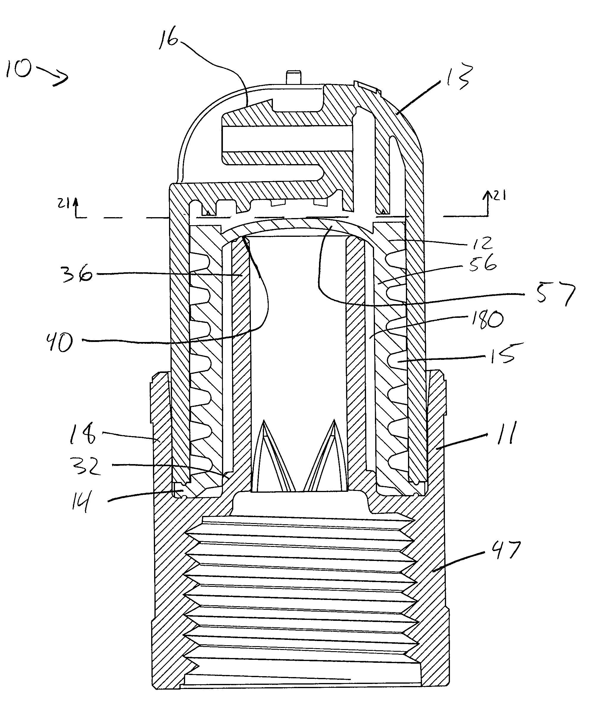
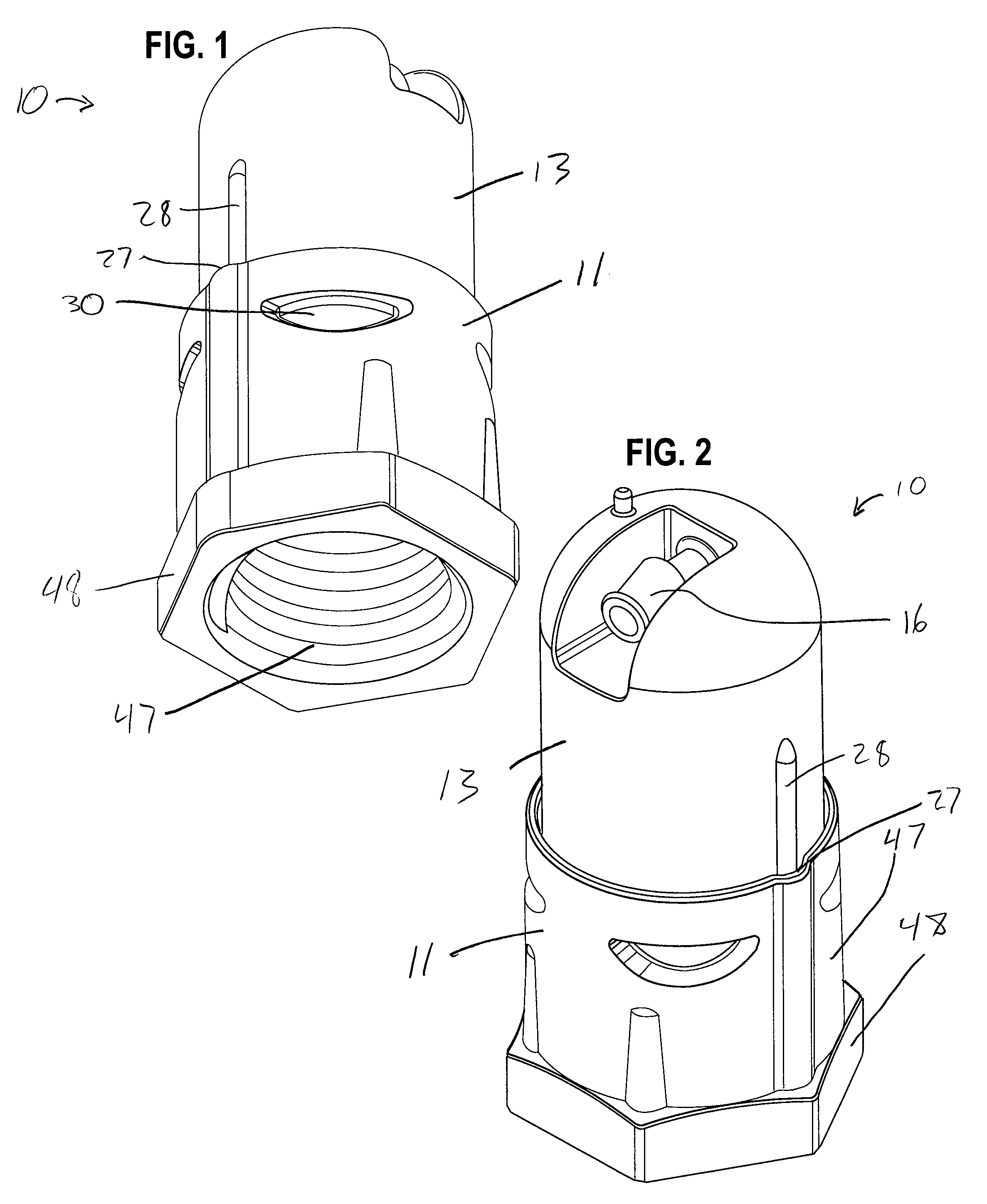
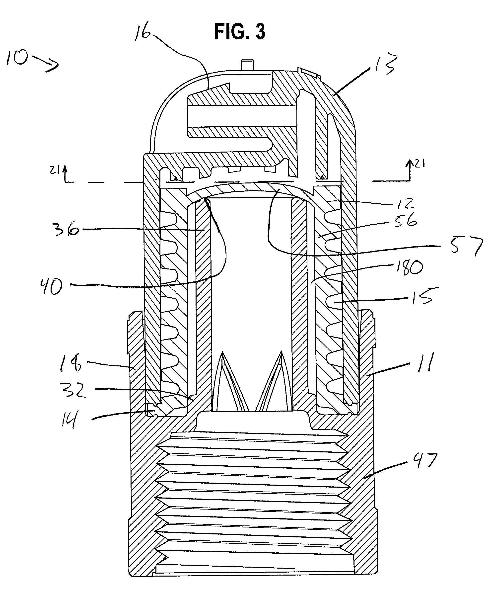
[0038]With reference to FIGS. 1-6, a drip irrigation emitter 10 is provided for delivering irrigation water from a water supply conduit (not shown), such as an irrigation supply tube, pipe, or other water supply apparatus, at a low volume, drip-like flow rate. The emitter 10 generally comprises an inlet component 11, a valve component 12, and an outlet component 13.

[0039]The inlet component 11, the valve component 12, and the outlet component 13 are generally assembled together such that the valve component 12 is disposed within the outlet component 13 and the outlet component 13 is interlocked with the inlet component 11. The valve component 12 is generally held in place by a flange 14 that is generally compressed between the inlet component 11 and the outlet component 13. The valve component 12 cooperates with the outlet component 13 to define a relatively long labyrinth flow channel 15. The emitter 10 generally converts relatively high supply pressure to a relatively low supply p...


PUM


Abstract

An irrigation emitter is provided for delivering irrigation water from a water supply conduit, such as an irrigation supply tube, pipe, or other water supply apparatus, at a low volume or drip-like flow rate. The emitter operates generally through the use of a relatively long flow channel that causes a pressure reduction between the water supply conduit and an emitter outlet. The emitter includes an inlet component for tapping a portion of the water flow from the water supply conduit and, when the water pressure is above a predetermined minimum level, directing the flow to and through the flow channel for subsequent discharge to a desired location. The emitter also may regulate to accommodate for changes in supply pressure. The emitter also may include automatic flushing to dislodge debris trapped within the emitter.

Description

FIELD[0001]The present invention relates to irrigation and, more particularly, to low flow irrigation emitters.BACKGROUND[0002]Low flow irrigation emitters (also referred to as “drip emitters”) are generally known in the art for use in delivering irrigation water at relatively low volume flow rate, thereby conserving water. Such irrigation devices commonly comprise an emitter housing connected to a water supply tube through which irrigation water is supplied under pressure. The drip irrigation device taps a portion of the relatively high pressure irrigation water from the supply tube for flow through a typically long or small cross-section flow path in the device to achieve a desired pressure drop prior to discharge at a drip-like flow rate. In a conventional system, a large number of the drip irrigation devices are mounted at selected positions along the length of the supply tube to deliver the irrigation water to a large number of specific points, such as directly to a plurality o...

Claims


Application Information

Patent Timeline
IPC IPC(8): B05B15/00
CPCF16K47/08F16K15/145A01G25/023
Inventor FEITH, RAYMOND P.MATTLIN, JEFFREY LEE
Owner RAIN BIRD CORP
Why Eureka
Try Eureka