Acoustic transducer for pulse-echo monitoring and control of thermally ablative lesioning in layered and nonlayered tissues, catheter contact monitoring, tissue thickness measurement and pre-pop warning

a technology of acoustic transducers and pulse-echo monitoring, which is applied in the field of acoustic transducers, can solve the problems of high cost of multi-fiber fiber-optic solutions, inability to fully blind the probe, and the inability to manufacture approaches which utilize 3 or more such optical fibers plus dedicated leds and photodiodes, and achieves a small french diameter. , the effect of cost reduction

Inactive Publication Date: 2014-01-14
ST JUDE MEDICAL
View PDF14 Cites 23 Cited by
  • Summary
  • Abstract
  • Description
  • Claims
  • Application Information

AI Technical Summary

Problems solved by technology

One potential disadvantage of optical techniques, other than the cost for a multi-fiber fiber-optic solution, is that tissue surface charring can partially blind the probe by blocking all light penetration at the tissue surface.
Approaches which utilize 3 or more such optical fibers plus dedicated LEDS and photodiodes can become expensive to manufacture and do not leave much room for other important catheter components such as catheter steering wires and fluid lumens.
They also will have a somewhat higher failure rate, higher manufacturing cost, and lower manufacturing yield given the large number of added components.
(a) It is a separate additional fairly expensive device.
It is not easy in a beating heart to find and remain aimed at the ablating catheter tip given that the 2D ICE image plane must be aligned perfectly with the ablating tip.
ICE imaging catheters are still eagerly employed by many practitioners today for general visualization of target anatomy but they do not yet provide useful lesion information for the above and additional reasons.

Method used


Image

  • Acoustic transducer for pulse-echo monitoring and control of thermally ablative lesioning in layered and nonlayered tissues, catheter contact monitoring, tissue thickness measurement and pre-pop warning
  • Acoustic transducer for pulse-echo monitoring and control of thermally ablative lesioning in layered and nonlayered tissues, catheter contact monitoring, tissue thickness measurement and pre-pop warning
  • Acoustic transducer for pulse-echo monitoring and control of thermally ablative lesioning in layered and nonlayered tissues, catheter contact monitoring, tissue thickness measurement and pre-pop warning

Examples


Embodiment Construction

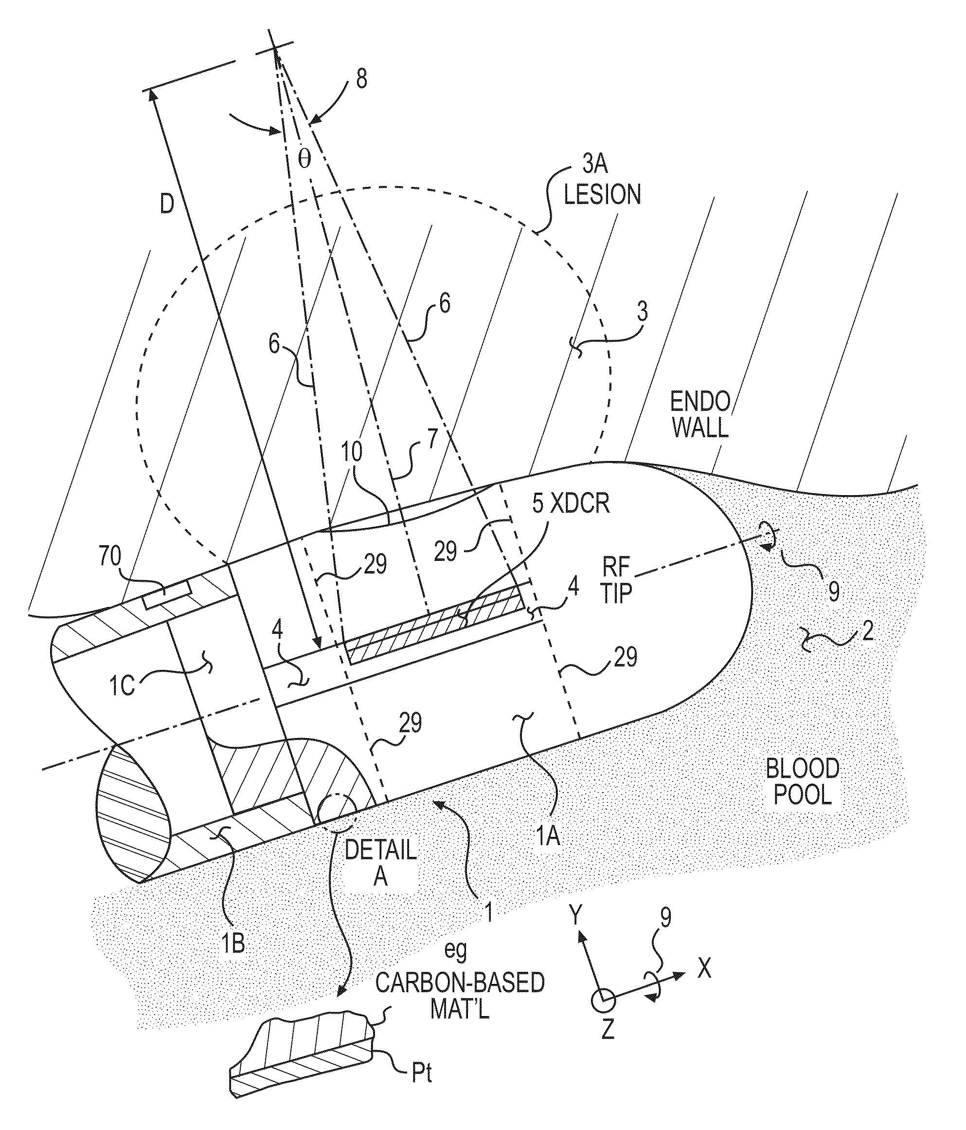
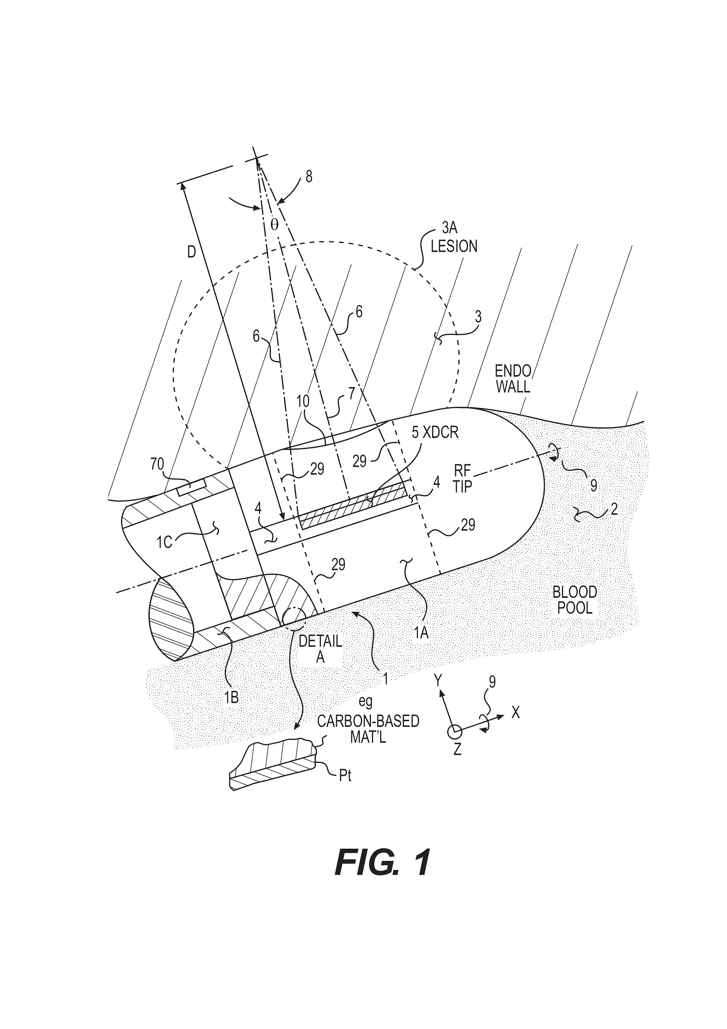
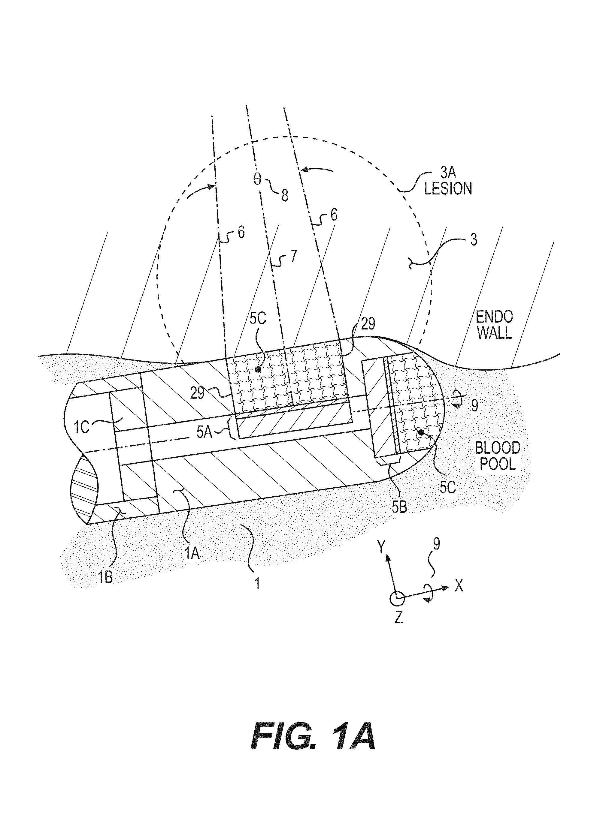
[0027]In the following detailed description of the invention, reference is made to the accompanying drawings which form a part of the disclosure, and in which are shown by way of illustration, and not of limitation, exemplary embodiments by which the invention may be practiced. In the drawings, like numerals describe substantially similar components throughout the several views. Further, it should be noted that while the detailed description provides various exemplary embodiments, as described below and as illustrated in the drawings, the present invention is not limited to the embodiments described and illustrated herein, but can extend to other embodiments, as would be known or as would become known to those skilled in the art. Reference in the specification to “one embodiment,”“this embodiment,” or “these embodiments” means that a particular feature, structure, or characteristic described in connection with the embodiment is included in at least one embodiment of the invention, a...


PUM


Abstract

An ablation catheter with acoustic monitoring comprises an elongated catheter body; a distal member disposed adjacent a distal end and including an ablation element to ablate a biological member at a target region outside the catheter body; and one or more acoustic transducers each configured to direct an acoustic beam toward a respective target ablation region and receive reflection echoes therefrom. The distal member includes a transducer housing in which the acoustic transducers are disposed, the transducer housing including at least one transducer window which is the only portion in the distal member through which the acoustic beam passes, at least the at least one transducer window portion of the distal member being made of a material comprising at least 50% carbon by volume, the transducer window material having an acoustic impedance between that of the acoustic transducers and that of the biological member.

Description

BACKGROUND OF THE INVENTION[0001]The present invention relates generally to acoustic transducers and, more specifically, to acoustic transducers for lesion feedback, catheter tip contact-monitoring, tissue thickness measurement, and pre-pop warning.[0002]Cardiac ablation practitioners would like lesion feedback and contact monitoring from their thermal (e.g., radiofrequency or RF) ablation catheters. They would preferably also like to further know the thickness of target tissues and the proximity of organs to be avoided such as the esophagus, aorta, and lungs. Finally, some warning of pre-pop conditions would also be quite valuable. By “contact” we mean at least verification of intimate tissue contact of the ablating catheter tip, and even more preferably, also the measurement of the actual contact force involved. The contact force is of interest in order to avoid unintended tissue puncture and to guarantee good ablative results.[0003]Electrically based RF ablation catheter lesion-f...

Claims


Application Information

Patent Timeline
Patent Type & Authority Patents(United States)
IPC IPC(8): A61B8/00
CPCA61B2018/00577A61B2019/528A61B8/4272A61N7/022A61B8/4477A61B18/1492A61B8/445A61B8/085A61B8/12A61B8/0858A61B2018/00023A61B2090/3784F04C2270/041
Inventor SLIWA, JOHNMA, ZHENYIMORSE, STEPHEN
Owner ST JUDE MEDICAL
Why Eureka
Try Eureka