
Rapid exchange bias laser catheter design

a laser catheter and bias technology, applied in the field of improved, can solve the problems of reduced blood and oxygen flow to the heart muscle, chest pain,

Active Publication Date: 2014-01-14
SPECTRANETICS
View PDF103 Cites 16 Cited by
  • Summary
  • Abstract
  • Description
  • Claims
  • Application Information

AI Technical Summary

Benefits of technology

The patent describes a catheter that has a laser delivery member and a guidewire. The catheter has a balloon that can be inflated to move the laser delivery member towards the center of the catheter. The catheter also has a ramp that helps to move the laser delivery member outward from the center of the catheter. The technical effect of this invention is to provide a catheter that can deliver laser energy to a targeted area with greater precision and accuracy.

Problems solved by technology

When the blockage is severe, the flow of blood and oxygen to the heart muscle is reduced, causing chest pain.
However, due to the configuration of the optical fibers in most prior art laser catheters, the clinician is able to ablate only material that is typically directly in front of the distal end of the catheter.

Method used


Image

  • Rapid exchange bias laser catheter design
  • Rapid exchange bias laser catheter design
  • Rapid exchange bias laser catheter design

Examples


first embodiment

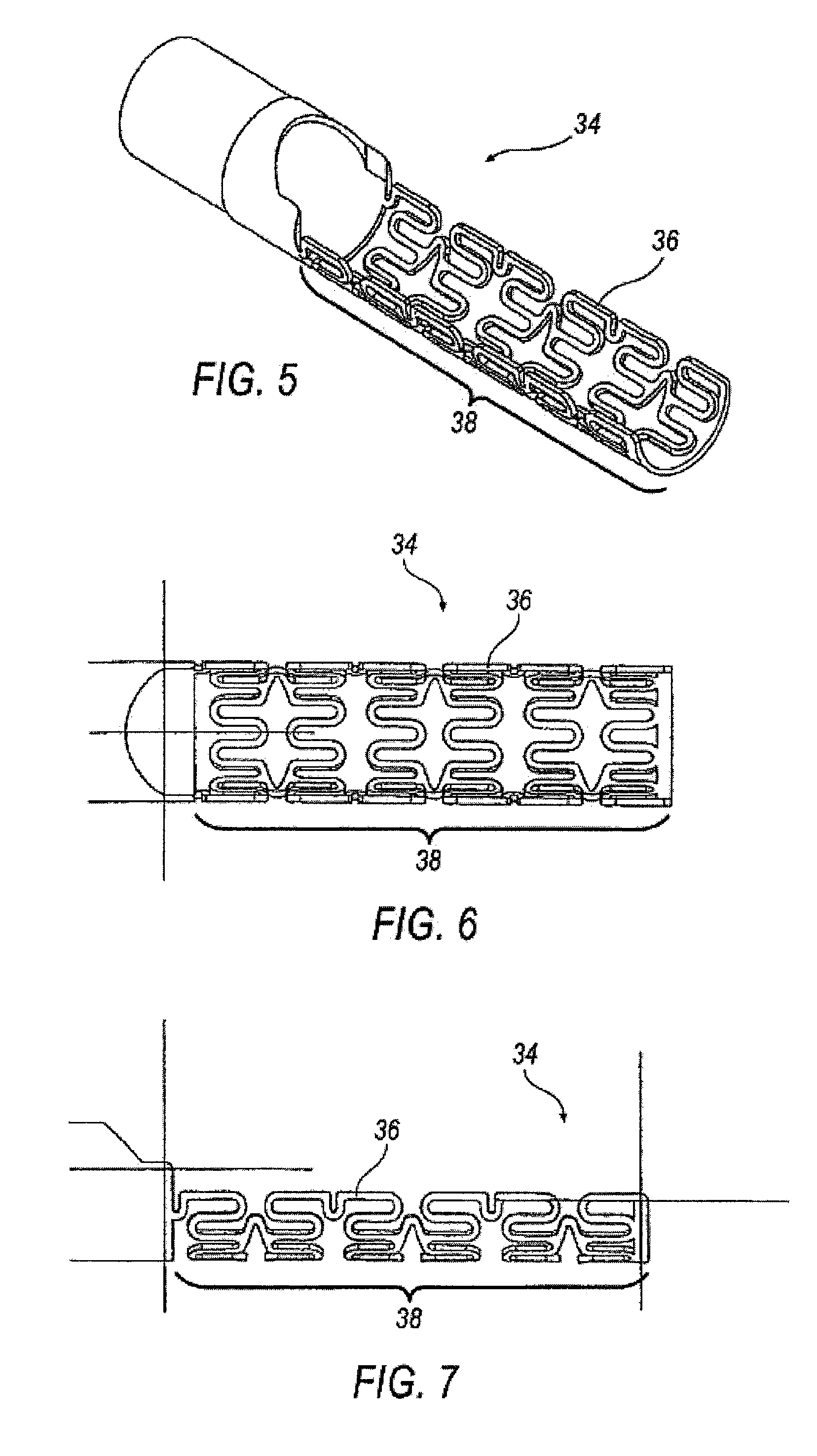
[0050]An alternative embodiment of the housing 12 comprises having at least one section at the first distal end 16. a support structure is support member 34 as shown in FIGS. 5-7. The support member 34 may be used to support the first distal end 16 while providing flexibility without producing failure. The first distal end 16 of the housing 12 may otherwise experience limited torsional and bending strength of the area around the cavity 18 specifically traversing bends having a radius of about 0.75 inches. The support member 34 assists in withstanding the torsional and bending forces when traversing bends of about 0.75 inches, while maintaining aspects of both integrity and functionality. In some embodiments, without limitation, support member 34 reinforces the area around the cavity 18 at the first distal end 16 with struts 36 forming a stent-like pattern 38. Support member 34 is formed from metal, plastic, or combinations thereof, and is at least partially axially disposed around t...

second embodiment

[0051]Referring to FIGS. 8 and 9, a support structure is shown as second support member 40 having a spring-like geometry 42. The support member 40 may be used to support the first distal end 16 while providing flexibility without producing failure. The second support member 40 acts as a backbone for the first distal end 16 of the housing 12. The spring-like geometry 42 permits flexing without causing failure. The height H of the spring-like geometry 42 may be of any height but is preferably below the centerline of the second support member 40. The ramp 20 may be molded over the spring like geometry 42 including having a top coat (not shown).

third embodiment

[0052]Referring to FIGS. 10 and 11, a support structure is shown as a third support member 44. The support member 44 may be used to support the first distal end 16 while providing flexibility without producing failure. The third support member 44 provides variable stiffness along the length of the member 44. Member 44 is the most rigid at rib 46 and most flexible at rib 48. This flexibility is accomplished by having the ribs increase in width W and distance D in addition to decreasing the side of a beam 50 as shown in FIG. 11. Beam 50 tapers from a first wide beam width BW1 to a narrower beam width BW2. A tip 52 having a tip length TL disposed at the distal end support member 44 functions to provide support for the first distal end 16 of the housing 12 while allowing additional flexibility. The ramp 20 may be molded over the spring-like geometry 42 including having a top coat (not shown). The support member length L may be varied depending on user requirements including varying the ...


PUM


Abstract

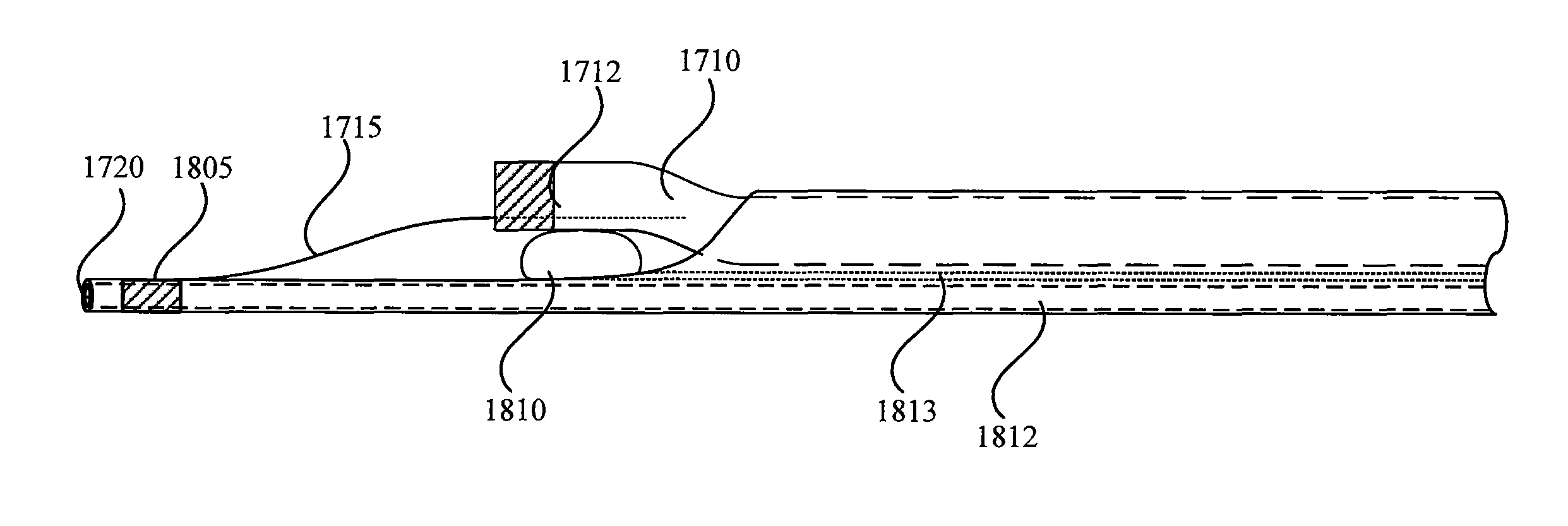
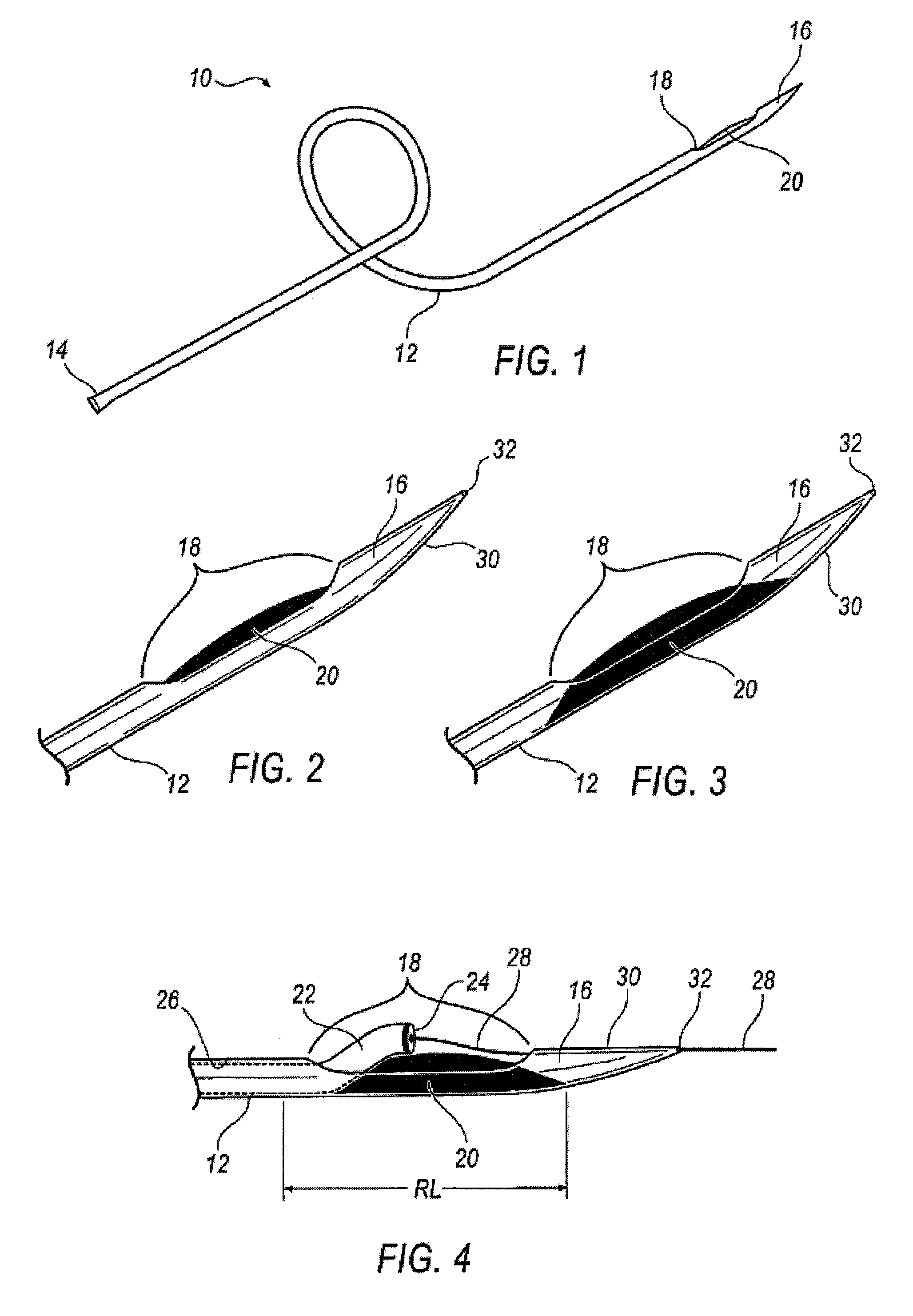
Embodiments of a balloon biasing laser catheter are provided. In some embodiments, the laser catheter may include a distal tip that extends from the distal end of the catheter from a point near the light guide aperture. The distal tip may be disposed at the periphery of the catheter. In some embodiments, a balloon may be disposed between the light guide aperture and the distal tip, such that the a light guide extending from the aperture may be disposed proximate with the distal tip having the balloon in between. A retaining wire may be coupled with the distal tip and slidably coupled with the light guide. The retaining wire may keep the light guide biased relatively parallel with the distal tip and / or the catheter body when the balloon is inflated. The light guide may include a guidewire lumen the extends to the distal end of the distal tip.

Description

CROSS-REFERENCES TO RELATED APPLICATIONS[0001]This application is a continuation in part of U.S. Non-Provisional application Ser. No. 11 / 228,845 filed on Sep. 16, 2006, which claims the benefit of U.S. Provisional Application Ser. No. 60 / 611,191 filed Sep. 17, 2004, which is hereby incorporated by reference in its entirety.TECHNICAL FIELD[0002]The embodiments described herein are generally directed to improved apparatus and methods for the delivery of laser energy, including without limitation, to a laser delivery catheter.BACKGROUND OF THE INVENTION[0003]Arteries are the primary blood vessels that are responsible for providing blood and oxygen to the heart muscle. Arterial disease occurs when arteries become narrowed or blocked by a buildup of plaque (as some examples, atherosclerotic plaque or other deposits). When the blockage is severe, the flow of blood and oxygen to the heart muscle is reduced, causing chest pain. Arterial blockage by clots formed in a human body may be reliev...

Claims


Application Information

Patent Timeline
Patent Type & Authority Patents(United States)
IPC IPC(8): A61B18/18
CPCA61B2017/22038A61B2018/2238A61B18/24A61B2017/22061A61B18/245
Inventor TAYLOR, KEVIN D.BOWE, WADE
Owner SPECTRANETICS
Learn More