Percutaneously-deliverable mechanical valve

a mechanical valve and percutaneous delivery technology, applied in the field of valve replacement, can solve the problems of increasing total stroke volume and reducing cardiac outpu

Active Publication Date: 2014-01-14
CARDIOVALVE LTD
View PDF21 Cites 280 Cited by
  • Summary
  • Abstract
  • Description
  • Claims
  • Application Information

AI Technical Summary

Benefits of technology

[0037]In an application, in the compressed configuration, the prosthetic valve has a greatest transverse diameter of less than 12 mm.
[0038]In an application, in the compressed configuration, the prosthetic valve has a greatest transverse diameter of less than 9 mm.
[0039]In an application, in the compressed configuration, the prosthetic valve has a greatest transverse diameter of less than 6 mm.

Problems solved by technology

Regurgitation of blood from the ventricle into the atrium results in increased total stroke volume and decreased cardiac output, and ultimate weakening of the ventricle secondary to a volume overload and a pressure overload of the atrium.

Method used


Image

  • Percutaneously-deliverable mechanical valve
  • Percutaneously-deliverable mechanical valve
  • Percutaneously-deliverable mechanical valve

Examples


Embodiment Construction

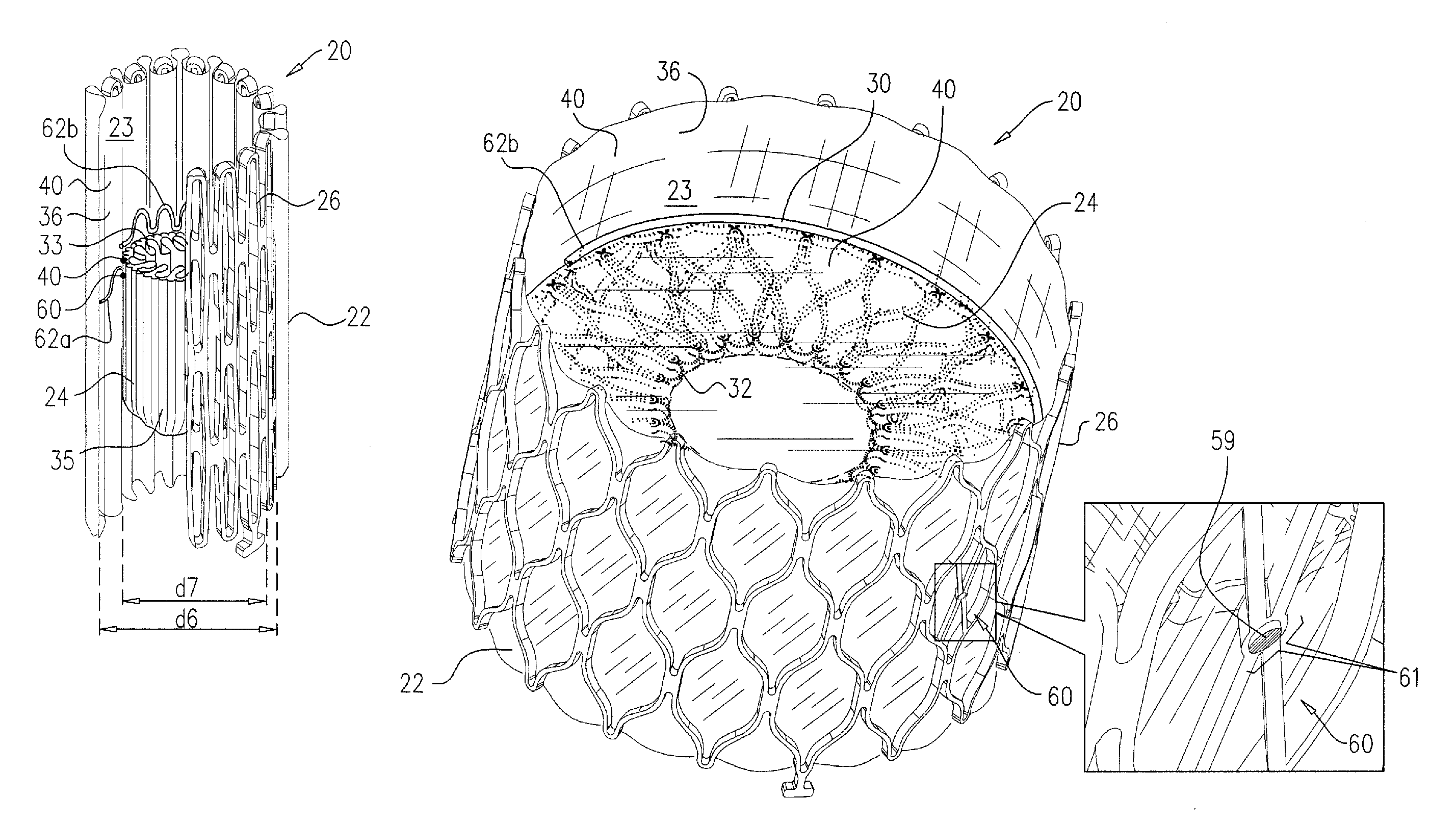
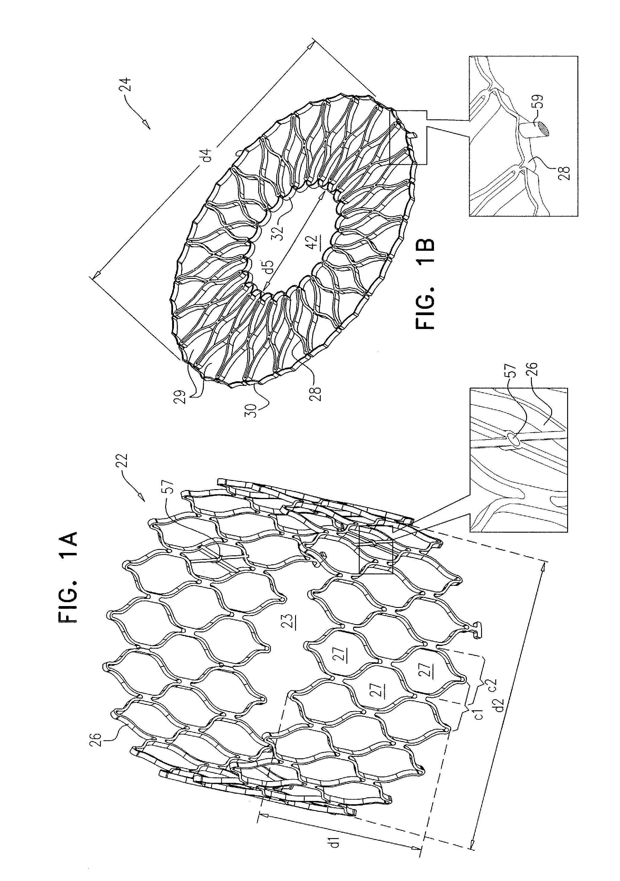
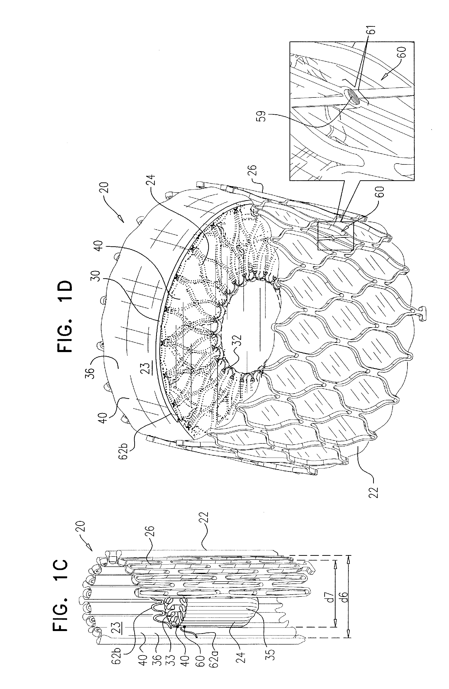
[0048]Reference is made to FIGS. 1A-D, which are schematic illustrations of a prosthetic valve 20, comprising a tubular element 22 and a valve member 24, in accordance with some applications of the invention. It is to be noted that throughout this application, including the specification and the claims, the term “valve member” is defined as the movable obstruction (e.g., inside the tubular element) that restricts and / or controls flow through the valve, as is known in the general valve art. Prosthetic valve 20 is configured to be placed in a lumen of the body of the subject, such as in a blood vessel and / or at a native valve of the subject. Typically, prosthetic valve 20 is configured to be placed at a native heart valve of a subject, and to replace native functionality of the native valve. FIG. 1A shows tubular element 22 alone, FIG. 1B shows valve member 23 alone, FIG. 1C shows valve 20 in a compressed configuration thereof, and FIG. 1D shows valve 20 in an expanded configuration t...


PUM


Abstract

Apparatus for regulating blood flow of a subject is provided, the apparatus comprising a prosthetic valve that comprises a tubular element, shaped to define a lumen therethrough; and a valve member, configured to be coupled to the tubular element and to be disposed within the lumen. The prosthetic valve has (1) a compressed configuration in which the lumen has a compressed width, the valve member is generally cylindrical, and the prosthetic valve is configured to be percutaneously delivered into the subject, and (2) an expanded configuration in which the lumen has an expanded width that is greater than the compressed width, and the valve member is generally disc-shaped, is coupled to the tubular element, and is disposed within the lumen. Other embodiments are also described.

Description

FIELD OF THE INVENTION[0001]Some applications of the present invention relate in general to valve replacement. More specifically, some applications of the present invention relate to prosthetic valves for replacement of a cardiac valve.BACKGROUND[0002]Ischemic heart disease causes regurgitation of a heart valve by the combination of ischemic dysfunction of the papillary muscles, and the dilatation of the ventricle that is present in ischemic heart disease, with the subsequent displacement of the papillary muscles and the dilatation of the valve annulus.[0003]Dilation of the annulus of the valve prevents the valve leaflets from fully coapting when the valve is closed. Regurgitation of blood from the ventricle into the atrium results in increased total stroke volume and decreased cardiac output, and ultimate weakening of the ventricle secondary to a volume overload and a pressure overload of the atrium.SUMMARY OF THE INVENTION[0004]A percutaneously-deliverable (e.g., transluminally-de...

Claims


Application Information

Patent Timeline
Patent Type & Authority Patents(United States)
IPC IPC(8): A61F2/24
CPCA61F2230/005A61F2230/0013A61F2/2469A61F2/2403A61F2/2418A61F2/2436A61F2220/0075A61F2/24A61F2220/0008A61F2220/0041A61F2/2409
Inventor HACOHEN, GILIZIPORY, YUVALREICH, TALMILLER, ERANGROSS, AMIR
Owner CARDIOVALVE LTD
Why Eureka
Try Eureka