Tank trailer having an air actuated handrail assembly

a tank trailer and air-actuated technology, applied in the field of tank trailers, can solve the problems of a substantial risk of operator falling off the tank, serious injury to himself or herself, and a higher probability of operator falling o

Active Publication Date: 2014-01-21
MAC TRAILER MFG
View PDF7 Cites 30 Cited by
  • Summary
  • Abstract
  • Description
  • Claims
  • Application Information

AI Technical Summary

Problems solved by technology

Some of the tank trailers that are currently in operation have relatively flat top walls but frequently these walls are fairly narrow for the operator to wall along.
Since these ports are raised relative to the top wall, they present a tripping hazard for the operator.
Since the top walls can be situated several feet off the road surface, there is a substantial risk for the operator to fall off the tank and seriously injure himself or herself.
Yet other tank trailers have curved top walls and the curvature thereof makes it even more likely that the operator will fall.

Method used


Image

  • Tank trailer having an air actuated handrail assembly
  • Tank trailer having an air actuated handrail assembly
  • Tank trailer having an air actuated handrail assembly

Examples


first embodiment

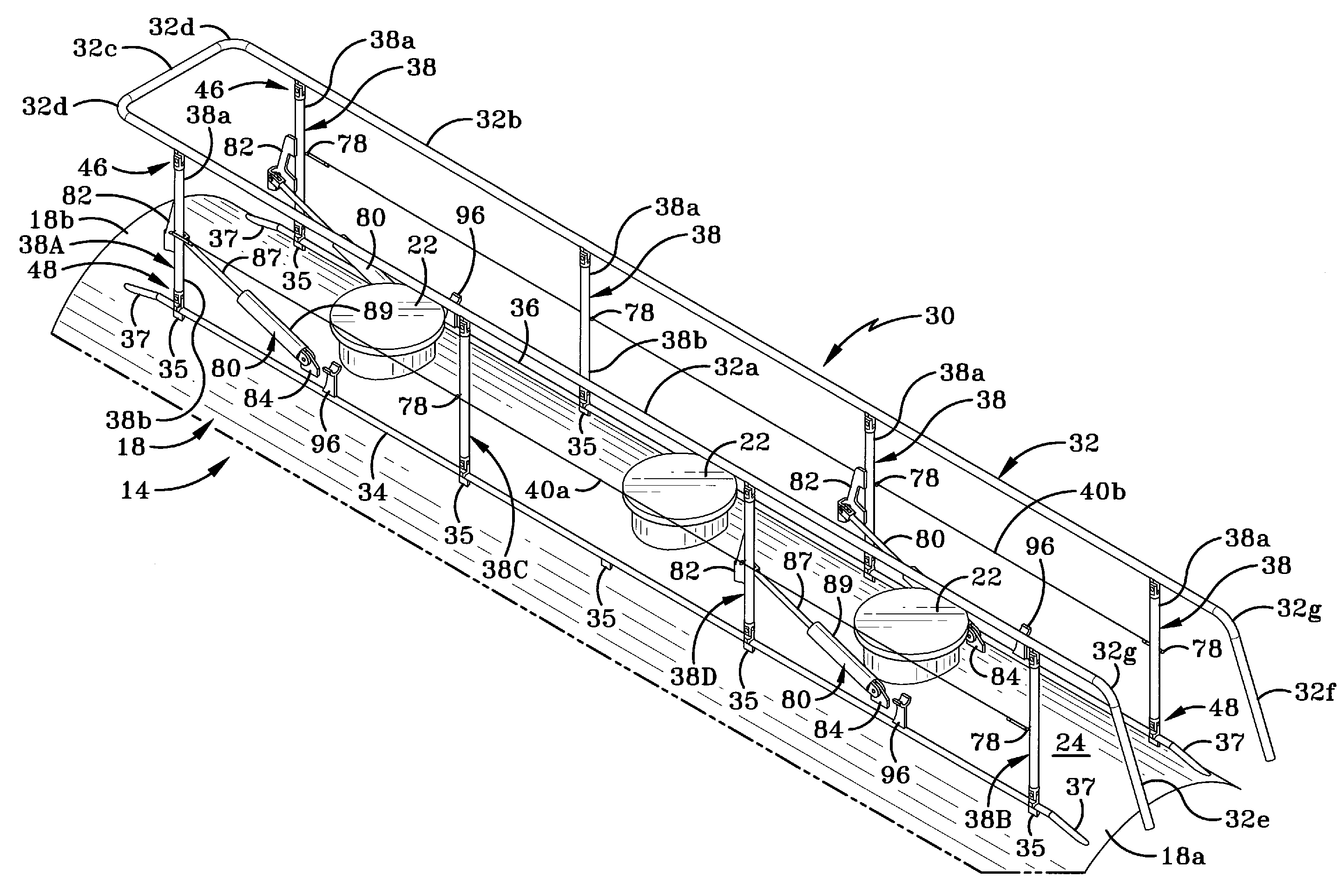
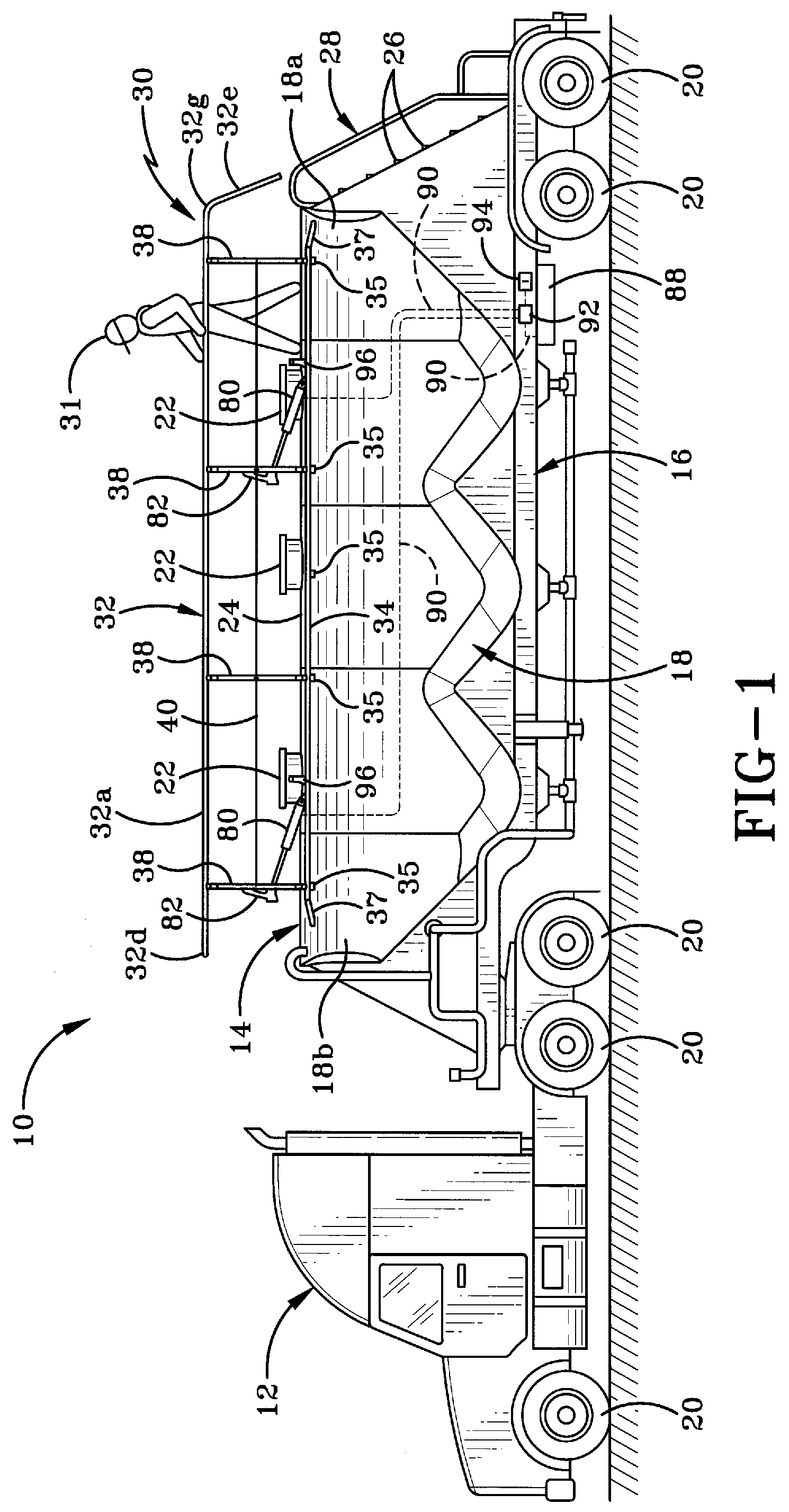
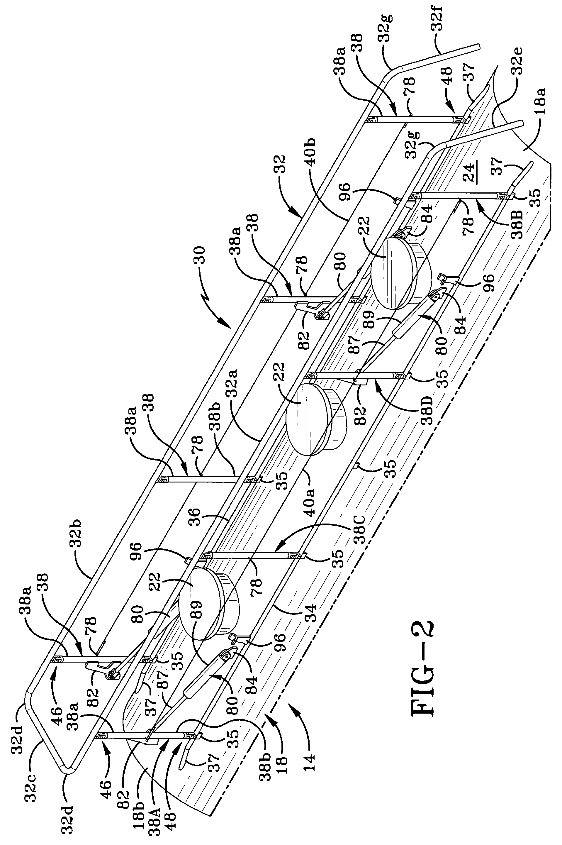
[0031]In accordance with a specific feature of the present invention, a collapsible handrail assembly 30 in accordance with the present invention is provided on tank 18. Handrail assembly 30 is provided so that operator 31 is able to walk along the top wall 24 in relative safety. Handrail assembly 30 is movable between an expanded position (FIG. 1) where it may be used by operator 31 to move safely along top wall 24 of tank 18, and a collapsed position (FIG. 14). When in the collapsed position, handrail assembly 30 is in disposed in close proximity to top wall 24 and is no longer available for use by operator 31. Preferably, when in the collapsed position, top rail 32 is disposed a distance “H” (FIG. 13) beneath the top surface of fill ports 22. Handrail assembly 30 is intended to be in the collapsed position when vehicle 10 is moving.

[0032]In accordance with a specific feature of the present invention, handrail assembly 30 preferably comprises a top rail 32 and a plurality of verti...

second embodiment

[0060]FIG. 15 shows a handrail assembly in accordance with the present invention, generally indicated at 130. Substantially the entire assembly 130 is identical to handrail assembly 30 with the exception of the configuration of the bottom rails 134, 136 and the second yoke assemblies 148. In this instance, bottom rails 134, 136 are substantially rectangular in cross-section and extend along the length of the tank 18. Each second yoke assembly 148 is comprised of a base member 64 and a cradle member 170. Base member 64 is substantially identical to the base member 64 of second yoke assembly 48. Cradle member 170 differs from cradle member 70 in that it is generally F-shaped and comprises a stem 170a, a leg 170b and an extension 170c. Stem 170a and leg 170b extend outwardly from extension and generally at right angles thereto. Stem 170a and leg 170b are substantially parallel to each other and are spaced a distance apart such that a gap (unnumbered) is defined therebetween. The gap is...


PUM


Abstract

A handrail assembly for a tank trailer and a yoke assembly for the same. Handrail assembly provides a safety device for an operator walking along a top wall of the tank trailer. The handrail assembly includes a top rail, a plurality of vertical members, a safety wire and, sometimes, a bottom rail. Each yoke assembly secures one of the top and bottom ends of the vertical members to either of the top and bottom rails or to a mounting bracket on the tank. Each yoke assembly includes a base member engaged partially in a bore of the vertical member, and a cradle member engaged with an exterior wall of the top or bottom rails or mounting bracket. Base and cradle members are secured together by a pivot pin. Fluid-actuated cylinders extending between the vertical members and the tank move the handrail assembly between collapsed and expanded positions.

Description

TECHNICAL FIELD[0001]This invention relates generally to trailers. More particularly, this invention relates to tank trailers. Specifically, this invention is directed to a tank trailer having an air actuated handrail assembly which aids in preventing operators from falling off the top wall of the tank trailer during filling and emptying operations and to a yoke assembly incorporated in the same.BACKGROUND INFORMATION[0002]Tank trailers are used in industry to transport a wide variety of products. Each trailer includes a large tank that has a plurality of fill ports on a top wall. When the tank is to be filled or to be emptied, the operator has to climb onto the top wall and walk along the same to open one or more of the fill ports. Some of the tank trailers that are currently in operation have relatively flat top walls but frequently these walls are fairly narrow for the operator to wall along. Additionally, if the operator has to open more than one fill port or a particular fill p...

Claims


Application Information

Patent Timeline
Patent Type & Authority Patents(United States)
IPC IPC(8): B60P3/22
CPCB60P3/22B60R3/005B60R21/02
Inventor CONNY, MICHAEL A.KIBLER, SCOTT A.
Owner MAC TRAILER MFG
Why Eureka
Try Eureka