Self guided subjective refraction instruments and methods

a subjective refraction and self-guided technology, applied in the field of self-guided subjective refraction instruments and methods, can solve the problems of patient participation, steep learning curve, difficulty in mastering the art,

Active Publication Date: 2014-01-21
LAI SHUI T
View PDF6 Cites 19 Cited by
  • Summary
  • Abstract
  • Description
  • Claims
  • Application Information

AI Technical Summary

Problems solved by technology

However, the current refraction methods have many challenges, including a steep learning curve, and difficulty in mastering the art, and it typically involves months of practice to learn to produce good prescriptions.
Another challenge is that it involves patient participation.
A wrong answer may lead the exam down a wrong path.
In the course of the refraction process, a patient may often ask to repeat the choices presented to them, because they are not sure or can't decide.
The repeated questioning causes anxiety on the part of the patient, and the lengthening of the eye exam time.
The knowing of the next move takes training, and it is a somewhat long and steep learning curve.
None has the reliability and accuracy that is comparable to a traditional phoropter.
Therefore, the outcomes of most objective refraction instrument tests are used as starting points, and not as acceptable final refraction results.
As it is said, the mastering of phoropter refraction is difficult, and involves months or years to perfect it.
One challenge during a refraction process is that a patient may often choose a higher negative power, because the letters appear darker and tighter, and are therefore perceived as being “sharper”.
However, this method sometimes fails when the patient adapts to the more minus power and rejects the less minus due to the locking mechanism of the muscle of the eye, that won't release the tension.
In other words, once a patient is over-minus, it is difficult to reverse it.
Wearing over-minus eyeglasses, patients tend to complain about headaches and dizziness, leading to a redoing or a remaking of the lens prescription, which costs lost time and unhappy patients.

Method used


Image

  • Self guided subjective refraction instruments and methods
  • Self guided subjective refraction instruments and methods
  • Self guided subjective refraction instruments and methods

Examples


Embodiment Construction

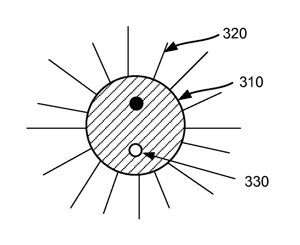
[0015]A refraction device is provided for determining a visual acuity and providing corrective optics for a test subject. The device includes an adjustable optical system and an adjustable viewing target disposed along an optical path such as to be viewable through the adjustable optical system by a test subject. The adjustable viewing target includes a directional indicator linked synchronously to at least two choices of corrective optics presented to the test subject.

[0016]The device may include an input device configured to be controlled by the test subject to indicate a direction suggested by the directional indicator for selecting between the at least two choices of corrective optics. The direction suggested by the directional indicator corresponds to a corrective optics choice as presented to the test subject by the viewing target.

[0017]The adjustable viewing target may be adjustable to at least two configurations each uniquely indicative of one of the choices of corrective op...


PUM


Abstract

A refraction device determines a refraction end point to provide corrective optics for a test subject. The device includes an adjustable optical system providing corrective optics to the test subject and an adjustable viewing target disposed along an optical path such as to be viewable through the adjustable optical system by a test subject. The adjustable viewing target includes a directional indicator linked synchronously to at least two choices of corrective optics presented to the test subject.

Description

BACKGROUND OF THE INVENTION[0001]Manifested refraction remains one of the most reliable methods of arriving at a prescription to correct refractive errors, whether it is used for preparing prescription eyeglasses or contact lenses, or for laser surgery. However, the current refraction methods have many challenges, including a steep learning curve, and difficulty in mastering the art, and it typically involves months of practice to learn to produce good prescriptions. Another challenge is that it involves patient participation. The end point comes after many steps, each involving a forced answer from the patient. The accuracy of each of the answers determines whether the entire eye test is moving in the correct direction. A wrong answer may lead the exam down a wrong path. In the course of the refraction process, a patient may often ask to repeat the choices presented to them, because they are not sure or can't decide. Repeating tests and steps in tests often is done to ensure accura...

Claims


Application Information

Patent Timeline
Patent Type & Authority Patents(United States)
IPC IPC(8): A61B3/10A61B3/02A61B3/00
CPCA61B3/032A61B3/0285A61B3/0016A61B3/0033A61B3/0041A61B3/0091A61B3/036A61B3/04
Inventor LAI, SHUI, T.
Owner LAI SHUI T
Why Eureka
Try Eureka