

Rotatable reverse metaglene
- Summary
- Abstract
- Description
- Claims
- Application Information
AI Technical Summary
Benefits of technology
Problems solved by technology
Method used
Image

Examples
Embodiment Construction
[0020]While the shoulder prosthesis described herein is susceptible to various modifications and alternative forms, specific embodiments thereof have been shown by way of example in the drawings and will herein be described in detail. It should be understood, however, that there is no intent to limit the shoulder prosthesis to the particular forms disclosed, but on the contrary, the intention is to cover all modifications, equivalents, and alternatives falling within the spirit and scope of the invention as defined by the appended claims.
[0021]As used herein, the terms “medial” and “lateral” are anatomical directional terms referring to positioning relative to the center of the body receiving the shoulder prosthesis. The term “medial” means closer to the center of the body. The term “lateral” means farther from the center of the body.
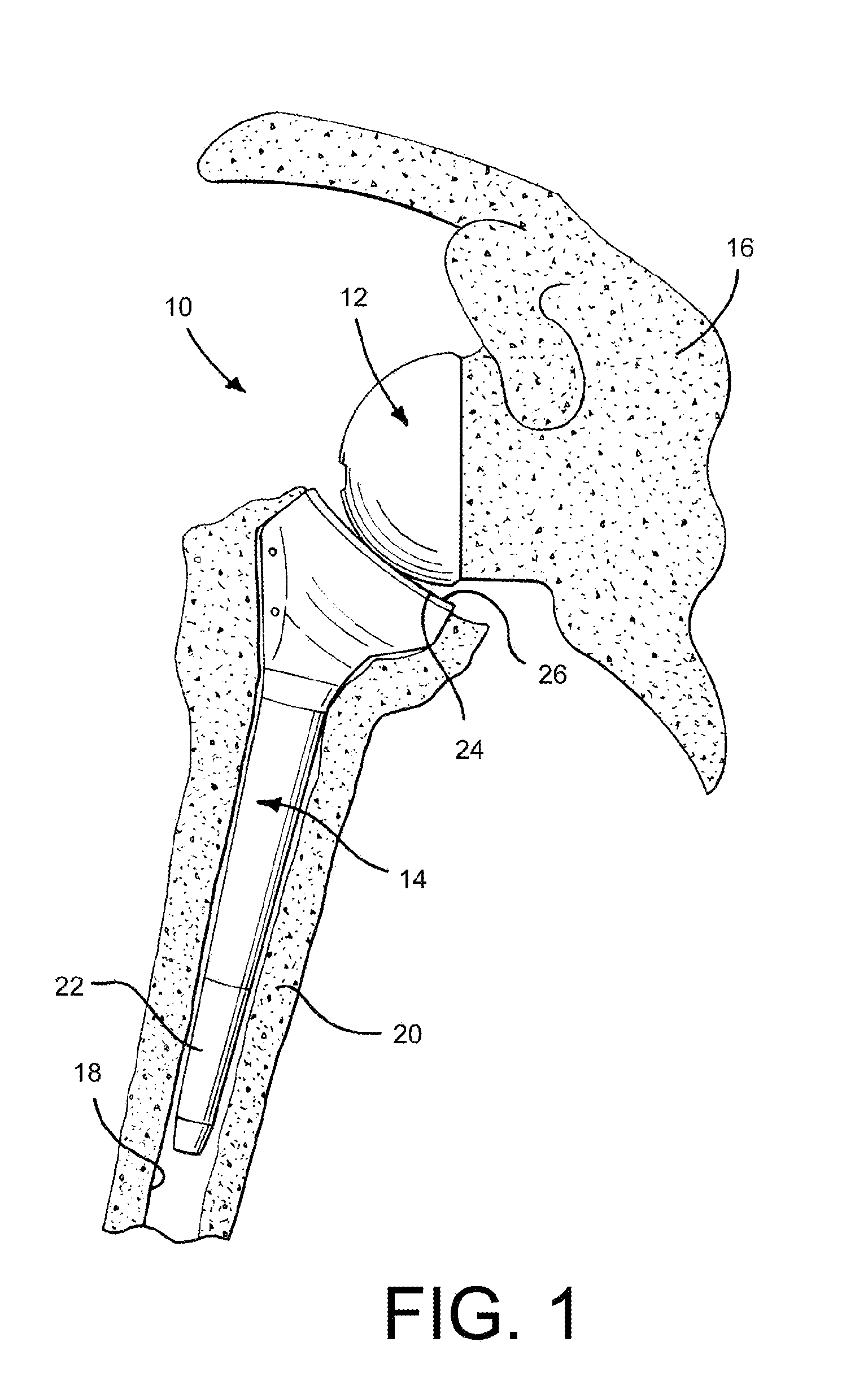
[0022]Referring to FIG. 1, there is shown a shoulder prosthesis 10 that includes a glenoid component 12 and a humeral component 14 that are configured ...
PUM
 Abstract
Description
Claims
Application Information